


VM-NR1677-02-3-a
VM-NR1677-02-3-a
NUREG/CR-1677: Volume 2, Benchmark Problem No. 3
Overview
| Reference: | NUREG/CR-1677 Volume II Piping Benchmark Problems, Dynamic Analysis Independent Support Motion Response Spectrum Method, P. Bezler, M. Subudhi & M. Hartzman of Brookhaven National Laboratory, prepared for the U.S. Nuclear Regulatory Commission, August 1985, Problem 3, pages 138-243. |
| Analysis Type(s): | |
| Element Type(s): | |
| Input Listing: |
Test Case
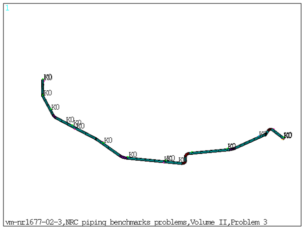
This benchmark problem is a two-anchor configuration simulating safety injection piping of a nuclear power plant as shown in Figure 628: FE Model of the Benchmark Problem. The support elements were a combination of spring and snubber elements. Modal and response spectrum analysis is performed on the piping model. The input excitation consisted of four spectra sets with the vertical component of excitation varying from set to set while the horizontal components of excitation are identical for all supports. Each solution has a fifteen natural frequency approximation with various spectra and spectrum weighting factors.
Response spectrum solutions are done for three cases:
Case 1: Envelope spectrum excitation
Case 2: Independent support excitation with SRSS combination
Case 3: Independent support excitation with absolute sum combination
| Material Properties | Geometric Properties | Loading | ||||||||||||||||||||||||
|---|---|---|---|---|---|---|---|---|---|---|---|---|---|---|---|---|---|---|---|---|---|---|---|---|---|---|
| Pipe Elements: Material ID 1:
Material ID 2:
Material ID 3:
Stiffness for Spring-Damper Elements (lb/in): Since there are multiple Spring Supports at different locations, the Stiffness for the Spring Damper Elements are listed based on real constant set number. Set 4:
Set 5:
Set 6:
Set 7:
Set 8:
Set 9:
Set 10:
| Straight Pipe: Set 1:
Bend Pipe: Set 2:
Set 3:
| Temperature = 400 F applied as body force. Pressure = 615 psi. applied as surface pressure. Case 1: Case 2: Case 3: |
Results Comparison
Table 75: Frequencies Obtained from Modal Solution:
| Mode | Target | Mechanical APDL | Ratio |
|---|---|---|---|
| 1 | 7.238 | 7.2431 | 1.000 |
| 2 | 10.145 | 10.1497 | 1.000 |
| 3 | 14.579 | 14.6066 | 1.000 |
| 4 | 15.991 | 16.0215 | 1.000 |
| 5 | 17.198 | 17.177 | 1.000 |
| 6 | 17.987 | 17.9922 | 1.000 |
| 7 | 22.282 | 22.274 | 1.000 |
| 8 | 23.632 | 23.6365 | 1.000 |
| 9 | 27.864 | 27.8631 | 1.000 |
| 10 | 29.211 | 29.207 | 1.000 |
| 11 | 29.514 | 29.4711 | 1.000 |
| 12 | 31.554 | 31.5635 | 1.000 |
| 13 | 34.018 | 34.0245 | 1.000 |
| 14 | 34.778 | 34.7638 | 1.000 |
| 15 | 35.122 | 35.1169 | 1.000 |
Case 1: Envelope spectrum excitation
Table 76: Maximum Displacements and Rotations
| Result Node | Target | Mechanical APDL | Ratio |
|---|---|---|---|
| UX at node36 | 0.6114 | 0.6054 | 0.990 |
| UY at node51 | 1.1035 | 1.1039 | 1.000 |
| UZ at node20 | 0.0062 | 0.0062 | 0.999 |
| ROTX at node44 | 0.0093 | 0.0093 | 1.000 |
| ROTY at node31 | 0.006 | 0.006 | 0.997 |
| ROTZ at node53 | 0.0133 | 0.0133 | 1.000 |
Table 77: Element Forces and Moments
| Result | Target | Mechanical APDL | Ratio |
|---|---|---|---|
| FY at node65 | 11.000 | 10.852 | 0.987 |
| FX at node66 | 7837.000 | 7783.639 | 0.993 |
| FX at node67 | 4472.000 | 4447.907 | 0.995 |
| FY at node75 | 8931.000 | 8936.619 | 1.001 |
| FY at node68 | 359.000 | 357.420 | 0.996 |
| FY at node69 | 729.000 | 719.789 | 0.987 |
| FY at node70 | 784.000 | 792.5824 | 1.011 |
| FY at node71 | 1043.000 | 1025.413 | 0.983 |
| FY at node72 | 1378.000 | 1361.234 | 0.988 |
| FY at node73 | 3408.000 | 3381.375 | 0.992 |
| FY at node74 | 1448.000 | 1435.296 | 0.991 |
| FX at node101 | 1685.000 | 1672.272 | 0.992 |
| FY at node102 | 87.000 | 87.303 | 1.003 |
| FZ at node103 | 1370.000 | 1363.138 | 0.995 |
| FX at node591 | 3031.000 | 2994.254 | 0.988 |
| FY at node592 | 15859.000 | 15871.962 | 1.001 |
| FZ at node593 | 896.000 | 886.978 | 0.990 |
| FX at node120 | 6792.000 | 6773.652 | 0.997 |
| FX at node310 | 11991.000 | 11957.218 | 0.997 |
| FX at node61 | 801.000 | 800.657 | 1.000 |
| FX at node62 | 303.000 | 303.116 | 1.000 |
| FX at node63 | 7447.000 | 7420.509 | 0.996 |
Table 78: Element Forces and Moments
| Result | Target | Mechanical APDL | Ratio |
|---|---|---|---|
| Element 1 | |||
| PX(I) | 2014.000 | 1997.825 | 0.992 |
| VY(I) | 86.890 | 87.303 | 1.005 |
| VZ(I) | 813.200 | 814.444 | 1.002 |
| TX(I) | 14130.000 | 13970.555 | 0.989 |
| MY(I) | 58340.000 | 58552.903 | 1.004 |
| MZ(I) | 3861.000 | 3879.502 | 1.005 |
| PX(J) | 2014.000 | 1997.825 | 0.992 |
| VY(J) | 86.89000 | 87.303 | 1.005 |
| VZ(J) | 813.2000 | 814.444 | 1.002 |
| TX(J) | 14130.000 | 13970.555 | 0.989 |
| MY(J) | 24430.000 | 24567.022 | 1.006 |
| MZ(J) | 535.000 | 525.835 | 0.983 |
| Element 17 | |||
| PX(I) | 6286.000 | 6272.340 | 0.998 |
| VY(I) | 752.300 | 742.262 | 0.987 |
| VZ(I) | 873.300 | 871.734 | 0.998 |
| TX(I) | 22430.000 | 22143.624 | 0.987 |
| MY(I) | 8460.000 | 8491.516 | 1.004 |
| MZ(I) | 29590.000 | 29012.529 | 0.980 |
| PX(J) | 6286.000 | 6272.340 | 0.998 |
| VY(J) | 752.300 | 742.262 | 0.987 |
| VZ(J) | 873.300 | 871.734 | 0.998 |
| TX(J) | 22430.000 | 22143.624 | 0.987 |
| MY(J) | 43530.000 | 43483.765 | 0.999 |
| MZ(J) | 23500.000 | 22462.707 | 0.956 |
| Element 50 | |||
| PX(I) | 1739.000 | 1726.048 | 0.993 |
| VY(I) | 395.300 | 387.095 | 0.979 |
| VZ(I) | 773.000 | 775.102 | 1.003 |
| TX(I) | 14640.000 | 14416.888 | 0.985 |
| MY(I) | 22240.000 | 22272.039 | 1.001 |
| MZ(I) | 16520.000 | 16382.506 | 0.992 |
| PX(J) | 1879.000 | 1868.924 | 0.995 |
| VY(J) | 395.300 | 387.095 | 0.979 |
| VZ(J) | 300.000 | 295.205 | 0.984 |
| TX(J) | 20260.000 | 20011.374 | 0.988 |
| MY(J) | 29470.000 | 29597.765 | 1.004 |
| MZ(J) | 16330.000 | 16300.507 | 0.998 |
Case 2: Independent support excitation with SRSS combination
Table 79: Maximum Displacements and Rotations Obtained from Spectrum Solve
| Result Node | Target | Mechanical APDL | Ratio |
|---|---|---|---|
| UX at node36 | 0.5674 | 0.5620 | 0.990 |
| UY at node51 | 0.3888 | 0.3854 | 0.991 |
| UZ at node36 | 0.5219 | 0.5163 | 0.989 |
| ROTX at node22 | 0.0028 | 0.0028 | 0.989 |
| ROTY at node22 | 0.0001 | 0.0001 | 0.997 |
| ROTZ at node35 | 0.0071 | 0.0070 | 0.990 |
Table 80: Reaction forces Obtained from Spectrum Solve
| Result Node | Target | Mechanical APDL | Ratio |
|---|---|---|---|
| FY at node65 | 4.000 | 3.838 | 0.960 |
| FX at node66 | 6845.000 | 6813.770 | 0.995 |
| FX at node67 | 3100.000 | 3082.6893 | 0.994 |
| FY at node75 | 2923.000 | 2900.109 | 0.992 |
| FY at node68 | 524.000 | 521.904 | 0.996 |
| FY at node69 | 1144.000 | 1138.868 | 0.996 |
| FY at node70 | 1068.000 | 1070.123 | 1.002 |
| FY at node71 | 1416.000 | 1405.368 | 0.992 |
| FY at node72 | 1666.000 | 1653.069 | 0.992 |
| FY at node73 | 2776.000 | 2759.1665 | 0.994 |
| FY at node74 | 1738.000 | 1725.100 | 0.993 |
| FX at node101 | 3160.000 | 3112.999 | 0.985 |
| FY at node102 | 109.000 | 109.196 | 1.002 |
| FZ at node103 | 2408.000 | 2375.430 | 0.986 |
| FX at node591 | 2834.000 | 2800.740 | 0.988 |
| FY at node592 | 4923.000 | 4890.870 | 0.993 |
| FZ at node593 | 803.000 | 798.011 | 0.994 |
| FX at node120 | 4953.000 | 4890.178 | 0.987 |
| FX at node61 | 831.000 | 826.212 | 0.994 |
| FX at node62 | 312.000 | 309.944 | 0.993 |
| FX at node63 | 4411.000 | 4373.316 | 0.991 |
| FX at node310 | 5898.000 | 5860.060 | 0.994 |
Table 81: Element Forces and Moments Obtained from Spectrum Solve
| Result | Target | Mechanical APDL | Ratio |
|---|---|---|---|
| Element 1 | |||
| PX(I) | 3807.000 | 3748.970 | 0.985 |
| VY(I) | 109.100 | 109.196 | 1.001 |
| VZ(I) | 1139.000 | 1130.767 | 0.993 |
| TX(I) | 17220.000 | 17067.318 | 0.991 |
| MY(I) | 77410.000 | 77027.059 | 0.995 |
| MZ(I) | 5027.000 | 5033.468 | 1.001 |
| PX(J) | 3807.000 | 3748.970 | 0.985 |
| VY(J) | 109.100 | 109.196 | 1.001 |
| VZ(J) | 1139.000 | 1130.767 | 0.993 |
| TX(J) | 17220.000 | 17067.318 | 0.991 |
| MY(J) | 30930.000 | 30861.332 | 0.998 |
| MZ(J) | 775.300 | 768.536 | 0.991 |
| Element 17 | |||
| PX(I) | 3539.000 | 3507.254 | 0.991 |
| VY(I) | 933.300 | 925.705 | 0.992 |
| VZ(I) | 533.100 | 529.442 | 0.993 |
| TX(I) | 26390.000 | 26106.583 | 0.989 |
| MY(I) | 9809.000 | 9800.492 | 0.999 |
| MZ(I) | 41630.000 | 41290.283 | 0.992 |
| PX(J) | 3539.000 | 3507.254 | 0.991 |
| VY(J) | 933.300 | 925.705 | 0.992 |
| VZ(J) | 533.100 | 529.442 | 0.993 |
| TX(J) | 26390.000 | 26106.583 | 0.989 |
| MY(J) | 29000.000 | 28900.249 | 0.997 |
| MZ(J) | 41980.000 | 41379.964 | 0.986 |
| Element 50 | |||
| PX(I) | 3150.000 | 3101.322 | 0.985 |
| VY(I) | 649.600 | 645.286 | 0.993 |
| VZ(I) | 1386.000 | 1379.109 | 0.995 |
| TX(I) | 17480.000 | 17252.674 | 0.987 |
| MY(I) | 28130.000 | 27958.296 | 0.994 |
| MZ(I) | 19150.000 | 18998.162 | 0.992 |
| PX(J) | 3413.000 | 3366.752 | 0.986 |
| VY(J) | 649.600 | 645.286 | 0.993 |
| VZ(J) | 444.200 | 430.259 | 0.969 |
| TX(J) | 23510.000 | 23242.522 | 0.989 |
| MY(J) | 38990.000 | 38842.244 | 0.996 |
| MZ(J) | 23530.000 | 23533.252 | 1.000 |
Case 3: Independent support excitation with absolute sum combination
Table 82: Maximum Displacements and Rotations Obtained from Spectrum Solve
| Result Node | Target | Mechanical APDL | Ratio |
|---|---|---|---|
| UX at node36 | 0.8272 | 0.8198 | 0.991 |
| UY at node51 | 0.5475 | 0.5452 | 0.996 |
| UZ at node36 | 0.7619 | 0.754 | 0.990 |
| ROTX at node12 | 0.0019 | 0.0019 | 0.990 |
| ROTY at node12 | 0.0002 | 0.0002 | 1.000 |
| ROTZ at node35 | 0.0103 | 0.0102 | 0.990 |
Table 83: Reaction forces Obtained from Spectrum Solve
| Result | Target | Mechanical APDL | Ratio |
|---|---|---|---|
| FY at node49 | 5.000 | 5.432 | 1.09 |
| FX at node55 | 9479.000 | 9411.998 | 0.99 |
| FX at node41 | 4250.000 | 4215.067 | 0.99 |
| FY at node41 | 4011.000 | 3999.962 | 1.00 |
| FY at node5 | 832.000 | 828.354 | 1.00 |
| FY at node8 | 1828.000 | 1818.031 | 0.99 |
| FY at node14 | 1689.000 | 1692.251 | 1.00 |
| FY at node20 | 2149.000 | 2131.734 | 0.99 |
| FY at node25 | 2467.000 | 2447.640 | 0.99 |
| FY at node290 | 4062.000 | 4039.442 | 0.99 |
| FY at node37 | 2537.000 | 2521.378 | 0.99 |
| FX at node1 | 4353.000 | 4303.772 | 0.99 |
| FY at node1 | 168.000 | 168.192 | 1.00 |
| FZ at node1 | 3376.000 | 3343.400 | 0.99 |
| FX at node59 | 3937.000 | 3885.033 | 0.99 |
| FY at node59 | 6819.000 | 6813.123 | 1.00 |
| FZ at node59 | 1069.000 | 1057.741 | 0.99 |
| FX at node13 | 6866.000 | 6796.337 | 0.99 |
| FX at node140 | 1276.000 | 1273.302 | 1.00 |
| FX at node18 | 492.544 | 490.815 | 1.00 |
| FX at node29 | 6332.010 | 6286.316 | 0.99 |
| FX at node32 | 8415.285 | 8375.552 | 1.00 |
Table 84: Element Forces and Moments Obtained from Spectrum Solve
| Result | Target | Mechanical APDL | Ratio |
|---|---|---|---|
| Element 1 | |||
| PX(I) | 5223.000 | 5162.199 | 0.988 |
| VY(I) | 167.900 | 168.192 | 1.002 |
| VZ(I) | 1753.000 | 1747.118 | 0.997 |
| TX(I) | 25590.000 | 25371.812 | 0.991 |
| MY(I) | 122100.000 | 121964.224 | 0.999 |
| MZ(I) | 7826.000 | 7836.310 | 1.001 |
| PX(J) | 5223.000 | 5162.199 | 0.988 |
| VY(J) | 167.900 | 168.192 | 1.002 |
| VZ(J) | 1753.000 | 1747.118 | 0.997 |
| TX(J) | 25590.000 | 25371.812 | 0.991 |
| MY(J) | 49880.000 | 49950.709 | 1.001 |
| MZ(J) | 1213.000 | 1202.718 | 0.992 |
| Element 17 | |||
| PX(I) | 4944.000 | 4905.012 | 0.992 |
| VY(I) | 1380.000 | 1368.650 | 0.992 |
| VZ(I) | 741.600 | 737.391 | 0.994 |
| TX(I) | 38460.000 | 38055.473 | 0.989 |
| MY(I) | 15200.000 | 15209.516 | 1.001 |
| MZ(I) | 63740.000 | 63190.025 | 0.991 |
| PX(J) | 4944.000 | 4905.012 | 0.992 |
| VY(J) | 1380.000 | 1368.650 | 0.992 |
| VZ(J) | 741.600 | 737.391 | 0.994 |
| TX(J) | 38460.000 | 38055.473 | 0.989 |
| MY(J) | 40840.000 | 40736.452 | 0.997 |
| MZ(J) | 67620.000 | 66625.670 | 0.985 |
| Element 50 | |||
| PX(I) | 4365.000 | 4314.227 | 0.988 |
| VY(I) | 1042.000 | 1034.289 | 0.993 |
| VZ(I) | 1942.000 | 1939.515 | 0.999 |
| TX(I) | 25740.000 | 25414.899 | 0.987 |
| MY(I) | 45220.000 | 45105.706 | 0.997 |
| MZ(I) | 27970.000 | 27760.288 | 0.993 |
| PX(J) | 4738.000 | 4692.080 | 0.990 |
| VY(J) | 1042.000 | 1034.289 | 0.993 |
| VZ(J) | 615.900 | 598.878 | 0.972 |
| TX(J) | 34210.000 | 33823.295 | 0.989 |
| MY(J) | 61630.000 | 61625.412 | 1.000 |
| MZ(J) | 37150.000 | 37130.922 | 0.999 |
Note: PX (I) and PX (J) = Section axial force at node I and J.
VY (I) and VY (J) = Section shear forces along Y direction at node I and J.
VZ (I) and VZ (J) = Section shear forces along Z direction at node I and J.
TX (I) and TX (J) = Section torsional moment at node I and J.
MY (I) and MY (J) = Section bending moments along Y direction at node I and J.
MZ (I) and MZ (J) = Section bending moments along Z direction at node I and J.
The element forces and moments along Y and Z directions are flipped between Mechanical APDL and NRC results.