


VM-NR1677-02-2-a
VM-NR1677-02-2-a
NUREG/CR-1677: Volume 2, Benchmark Problem No. 2
Overview
| Reference: | NUREG/CR-1677 Volume II Piping Benchmark Problems, Dynamic Analysis Independent Support Motion Response Spectrum Method, P. Bezler, M. Subudhi & M. Hartzman of Brookhaven National Laboratory, prepared for the U.S. Nuclear Regulatory Commission, August 1985, Problem 2, pages 77-137. |
| Analysis Type(s): | |
| Element Type(s): | |
| Input Listing: |
Test Case
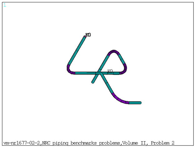
This benchmark problem is a three-branch configuration as shown in Figure 627: FE model of the Benchmark Problem. The support elements were divided into four groups corresponding to four distinct excitation sets. Modal and response spectrum analysis is performed on the model. Each solution had a twenty-five frequency approximation with various spectrum weighting factors. Response spectrum solutions are done for three cases:
Case 1: Envelope spectrum excitation
Case 2: Independent support excitation with SRSS combination
Case 3: Independent support excitation with absolute sum combination
Frequencies obtained from modal solve and the nodal/element solution obtained from spectrum solve are compared against reference results.
| Material Properties | Geometric Properties | Loading | |||||||||||||||
|---|---|---|---|---|---|---|---|---|---|---|---|---|---|---|---|---|---|
Pipe Element: Material ID 1:
Material ID 2:
Mass Element (lb-sec2/in): (Isotropic Mass) Set 6:
Stiffness for Spring-Damper Elements (lb/in): Since there are multiple Spring Supports at different locations, the Stiffness for the Spring Damper Elements are listed based on real constant set number. Set 3:
Set 4:
Set 5:
| Straight Pipe: Set 1:
Set 2:
| Internal Pressure = 350 psi is applied internally on PIPE elements. Case 1: Case 2: Case 3: |
Results Comparison
Table 65: Frequencies Obtained from Modal Solution:
| Mode | Target | Mechanical APDL | Ratio |
|---|---|---|---|
| 1 | 9.360 | 9.1655 | 0.980 |
| 2 | 12.706 | 12.6533 | 1.000 |
| 3 | 15.377 | 15.1847 | 0.990 |
| 4 | 17.797 | 17.4952 | 0.980 |
| 5 | 21.603 | 21.2461 | 0.980 |
| 6 | 25.098 | 24.7136 | 0.980 |
| 7 | 32.035 | 31.771 | 0.990 |
| 8 | 38.069 | 37.7442 | 0.990 |
| 9 | 40.293 | 39.9244 | 0.990 |
| 10 | 48.898 | 48.2221 | 0.990 |
| 11 | 57.515 | 57.0146 | 0.990 |
| 12 | 61.500 | 61.0477 | 0.990 |
| 13 | 62.541 | 62.0268 | 0.990 |
| 14 | 69.348 | 68.4341 | 0.990 |
| 15 | 77.444 | 76.179 | 0.980 |
| 16 | 78.881 | 77.7516 | 0.990 |
| 17 | 101.715 | 99.622 | 0.980 |
| 18 | 103.583 | 101.6221 | 0.980 |
| 19 | 107.966 | 106.1587 | 0.980 |
| 20 | 115.098 | 112.7788 | 0.980 |
| 21 | 135.244 | 132.6403 | 0.980 |
| 22 | 155.220 | 153.8602 | 0.990 |
| 23 | 160.601 | 158.8719 | 0.990 |
| 24 | 203.789 | 200.4281 | 0.980 |
| 25 | 209.925 | 206.9838 | 0.990 |
Case 1: Envelope Spectrum Excitation
Table 66: Maximum Displacements and Rotations Obtained from Spectrum Solve
| Result Node | Target | Mechanical APDL | Ratio |
|---|---|---|---|
| UX at node14 | 0.0849 | 0.0913 | 1.075 |
| UY at node8 | 0.0379 | 0.0393 | 1.037 |
| UZ at node4 | 0.0907 | 0.0972 | 1.072 |
| ROTX at node3 | 0.001 | 0.0011 | 1.073 |
| ROTY at node7 | 0.0019 | 0.002 | 1.076 |
| ROTZ at node17 | 0.0009 | 0.001 | 1.071 |
Table 67: Reaction forces Obtained from Spectrum Solve
| Result Node | Target | Mechanical APDL | Ratio |
|---|---|---|---|
| FY at node23 | 65.000 | 64.858 | 0.998 |
| FX at node26 | 446.000 | 448.117 | 1.005 |
| FY at node28 | 164.000 | 165.698 | 1.010 |
| FX at node33 | 378.000 | 381.136 | 1.008 |
| FY at node34 | 192.000 | 193.067 | 1.006 |
Table 68: Element Forces and Moments Obtained from Spectrum Solve
| Result | Target | Mechanical APDL | Ratio |
|---|---|---|---|
| Element 1 | |||
| PX(I) | 64.960 | 64.858 | 0.998 |
| VY(I) | 90.500 | 93.048 | 1.028 |
| VZ(I) | 177.400 | 184.917 | 1.042 |
| TX(I) | 5110.000 | 5301.549 | 1.037 |
| MY(I) | 16350.000 | 17315.366 | 1.059 |
| MZ(I) | 7002.000 | 7418.061 | 1.059 |
| PX(J) | 64.960 | 64.858 | 0.998 |
| VY(J) | 90.500 | 93.048 | 1.028 |
| VZ(J) | 177.400 | 184.917 | 1.042 |
| TX(J) | 5110.000 | 5301.549 | 1.037 |
| MY(J) | 7138.000 | 7680.016 | 1.076 |
| MZ(J) | 3188.000 | 3382.535 | 1.061 |
| Element 20 | |||
| PX(I) | 245.100 | 246.391 | 1.005 |
| VY(I) | 191.600 | 193.067 | 1.008 |
| VZ(I) | 377.900 | 381.136 | 1.009 |
| TX(I) | 2314.000 | 2383.259 | 1.030 |
| MY(I) | 3823.000 | 4009.387 | 1.049 |
| MZ(I) | 3268.000 | 3271.878 | 1.001 |
| PX(J) | 245.100 | 246.391 | 1.005 |
| VY(J) | 191.600 | 193.067 | 1.008 |
| VZ(J) | 377.900 | 381.136 | 1.009 |
| TX(J) | 2314.000 | 2383.259 | 1.030 |
| MY(J) | 16600.000 | 17087.900 | 1.029 |
| MZ(J) | 11140.000 | 11205.551 | 1.006 |
| Element 8 | |||
| PX(I) | 446.300 | 461.294 | 1.034 |
| VY(I) | 32.560 | 33.799 | 1.038 |
| VZ(I) | 517.800 | 532.454 | 1.028 |
| TX(I) | 2967.000 | 3065.565 | 1.033 |
| MY(I) | 12020.000 | 12115.559 | 1.008 |
| MZ(I) | 798.600 | 804.853 | 1.008 |
| PX(J) | 664.800 | 686.096 | 1.032 |
| VY(J) | 32.560 | 33.799 | 1.038 |
| VZ(J) | 159.100 | 159.911 | 1.005 |
| TX(J) | 2021.000 | 2071.720 | 1.025 |
| MY(J) | 20520.000 | 20840.868 | 1.016 |
| MZ(J) | 2487.000 | 2574.882 | 1.035 |
Case 2: Independent Support Excitation with SRSS Combination
Table 69: Maximum Displacements and Rotations Obtained from Spectrum Solve
| Result Node | Target | Mechanical APDL | Ratio |
|---|---|---|---|
| UX at node14 | 0.0530 | 0.0574 | 1.082 |
| UY at node7 | 0.0242 | 0.0252 | 1.043 |
| UZ at node4 | 0.0574 | 0.0619 | 1.078 |
| ROTX at node3 | 0.0006 | 0.0007 | 1.08 |
| ROTY at node7 | 0.0012 | 0.0013 | 1.082 |
| ROTZ at node17 | 0.0006 | 0.0006 | 1.078 |
Table 70: Reaction forces Obtained from Spectrum Solve
| Result Node | Target | Mechanical APDL | Ratio |
|---|---|---|---|
| FY at node23 | 46.000 | 46.533 | 1.012 |
| FY at node28 | 98.000 | 99.526 | 1.016 |
| FZ at node35 | 116.000 | 115.203 | 0.993 |
Table 71: Element Forces and Moments Obtained from Spectrum Solve
| Result | Target | Mechanical APDL | Ratio |
|---|---|---|---|
| Element 1 | |||
| PX(I) | 46.1600 | 46.5337 | 1.008 |
| VY(I) | 53.0500 | 54.7907 | 1.033 |
| VZ(I) | 112.9000 | 117.7437 | 1.043 |
| TX(I) | 3230.0000 | 3369.8260 | 1.043 |
| MY(I) | 10340.0000 | 11008.9986 | 1.065 |
| MZ(I) | 4209.0000 | 4485.8240 | 1.066 |
| PX(J) | 46.1600 | 46.5337 | 1.008 |
| VY(J) | 53.0500 | 54.7907 | 1.033 |
| VZ(J) | 112.9000 | 117.7437 | 1.043 |
| TX(J) | 3230.0000 | 3369.8260 | 1.043 |
| MY(J) | 4529.0000 | 4898.8517 | 1.082 |
| MZ(J) | 2005.0000 | 2141.7982 | 1.068 |
| Element 20 | |||
| PX(I) | 115.5000 | 115.2037 | 0.997 |
| VY(I) | 114.0000 | 115.4438 | 1.013 |
| VZ(I) | 103.2000 | 100.8049 | 0.977 |
| TX(I) | 1361.0000 | 1408.4573 | 1.035 |
| MY(I) | 2302.0000 | 2391.9304 | 1.039 |
| MZ(I) | 1960.0000 | 1974.6510 | 1.007 |
| PX(J) | 115.5 | 115.2037 | 0.997 |
| VY(J) | 114.00 | 115.4438 | 1.013 |
| VZ(J) | 103.200 | 100.8049 | 0.977 |
| TX(J) | 1361.00 | 1408.4573 | 1.035 |
| MY(J) | 4038.0000 | 4167.3920 | 1.032 |
| MZ(J) | 6632.0000 | 6706.0262 | 1.011 |
| Element 8 | |||
| PX(I) | 265.00 | 275.8397 | 1.041 |
| VY(I) | 22.82 | 23.8785 | 1.046 |
| VZ(I) | 327.2 | 338.6018 | 1.035 |
| TX(I) | 1884.00 | 1958.7920 | 1.04 |
| MY(I) | 7379.0000 | 7503.3873 | 1.017 |
| MZ(I) | 763.8000 | 766.6107 | 1.004 |
| PX(J) | 411.6000 | 427.9288 | 1.040 |
| VY(J) | 22.8200 | 23.8785 | 1.046 |
| VZ(J) | 89.0400 | 87.2679 | 0.98 |
| TX(J) | 1346.00 | 1384.6321 | 1.029 |
| MY(J) | 12880.00 | 13181.8828 | 1.023 |
| MZ(J) | 1569.00 | 1637.1861 | 1.043 |
Case 3: Independent Support Excitation with Absolute Sum Combination
Table 72: Maximum Displacements and Rotations Obtained from Spectrum Solve
| Result Node | Target | Mechanical APDL | Ratio |
|---|---|---|---|
| UX at node14 | 0.0741 | 0.0797 | 1.076 |
| UY at node8 | 0.0355 | 0.0369 | 1.039 |
| UZ at node4 | 0.08 | 0.0858 | 1.072 |
| ROTX at node3 | 0.0009 | 0.0010 | 1.074 |
| ROTY at node7 | 0.0017 | 0.0018 | 1.076 |
| ROTZ at node17 | 0.0008 | 0.0009 | 1.072 |
Table 73: Reaction forces Obtained from Spectrum Solve
| Result | Target | Mechanical APDL | Ratio |
|---|---|---|---|
| FX at node1 | 76.000 | 78.580 | 1.03 |
| FY at node1 | 70.000 | 69.809 | 1.00 |
| FZ at node1 | 156.000 | 161.944 | 1.04 |
| FZ at node7 | 607.000 | 629.228 | 1.04 |
| FX at node9 | 350.000 | 352.638 | 1.01 |
| FY at node11 | 184.000 | 187.426 | 1.02 |
| FY at node 13 | 146.000 | 147.613 | 1.01 |
| FX at node 15 | 301.000 | 305.961 | 1.02 |
| FX at node17 | 45.000 | 46.520 | 1.03 |
| FY at node17 | 169.000 | 171.561 | 1.02 |
| FZ at node17 | 91.000 | 92.568 | 1.02 |
| FX at node21 | 152.000 | 148.172 | 0.97 |
| FY at node21 | 170.000 | 171.553 | 1.01 |
| FZ at node21 | 158.000 | 156.957 | 0.99 |
Table 74: Element Forces and Moments Obtained from Spectrum Solve
| Result | Target | Mechanical APDL | Ratio |
|---|---|---|---|
| Element 1 | |||
| PX(I) | 69.61 | 69.809 | 1.003 |
| VY(I) | 76.39 | 78.580 | 1.029 |
| VZ(I) | 155.6 | 161.944 | 1.041 |
| TX(I) | 4498 | 4667.308 | 1.038 |
| MY(I) | 14380 | 15231.297 | 1.059 |
| MZ(I) | 5959 | 6310.483 | 1.059 |
| PX(J) | 69.61 | 69.809 | 1.003 |
| VY(J) | 76.39 | 78.580 | 1.029 |
| VZ(J) | 155.6 | 161.944 | 1.041 |
| TX(J) | 4498 | 4667.308 | 1.038 |
| MY(J) | 6317 | 6795.559 | 1.076 |
| MZ(J) | 2787 | 2964.103 | 1.064 |
| Element 20 | |||
| PX(I) | 157.6 | 156.957 | 0.996 |
| VY(I) | 169.9 | 171.554 | 1.01 |
| VZ(I) | 151.7 | 148.172 | 0.977 |
| TX(I) | 2041 | 2103.856 | 1.031 |
| MY(I) | 3192 | 3304.303 | 1.035 |
| MZ(I) | 2935 | 2946.545 | 1.004 |
| PX(J) | 157.6 | 156.957 | 0.996 |
| VY(J) | 169.9 | 171.554 | 1.01 |
| VZ(J) | 151.7 | 148.172 | 0.977 |
| TX(J) | 2041 | 2103.856 | 1.031 |
| MY(J) | 6079 | 6239.911 | 1.026 |
| MZ(J) | 9904 | 9984.300 | 1.008 |
| Element 8 | |||
| PX(I) | 368.6 | 382.363 | 1.037 |
| VY(I) | 33.77 | 35.351 | 1.047 |
| VZ(I) | 453.2 | 466.924 | 1.03 |
| TX(I) | 2643 | 2723.367 | 1.03 |
| MY(I) | 10310 | 10419.421 | 1.011 |
| MZ(I) | 1268 | 1273.659 | 1.004 |
| PX(J) | 571.7 | 591.776 | 1.035 |
| VY(J) | 33.77 | 35.351 | 1.047 |
| VZ(J) | 120 | 118.409 | 0.987 |
| TX(J) | 1937 | 1981.184 | 1.023 |
| MY(J) | 17940 | 18258.859 | 1.018 |
| MZ(J) | 2187 | 2268.179 | 1.037 |
Note: PX (I) and PX (J) = Section axial force at node I and J.
VY (I) and VY (J) = Section shear forces along Y direction at node I and J.
VZ (I) and VZ (J) = Section shear forces along Z direction at node I and J.
TX (I) and TX (J) = Section torsional moment at node I and J.
MY (I) and MY (J) = Section bending moments along Y direction at node I and J.
MZ (I) and MZ (J) = Section bending moments along Z direction at node I and J.
The element forces and moments along Y and Z directions are flipped between Mechanical APDL and NRC results.