


VM-NR1677-02-1-a
VM-NR1677-02-1-a
NUREG/CR-1677: Volume 2, Benchmark Problem No. 1
Overview
| Reference: | NUREG/CR-1677 Volume II Piping Benchmark Problems, Dynamic Analysis Independent Support Motion Response Spectrum Method, P. Bezler, M. Subudhi & M. Hartzman of Brookhaven National Laboratory, prepared for the U.S. Nuclear Regulatory Commission, August 1985, Problem 1, pages 18-76. |
| Analysis Type(s): | |
| Element Type(s): | |
| Input Listing: |
Test Case
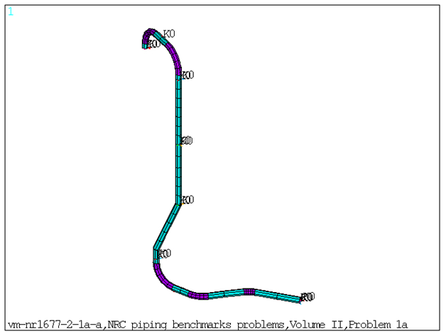
This benchmark problem simulates a 3.5 inch diameter water line extending between two elevations and having two anchors and numerous intermediate supports. The system configuration is shown in Figure 626: FE Model of the Benchmark Problem. Modal and response spectrum analysis is performed on the piping model. Each solution has a fifteen frequency approximation with appropriate spectra and spectrum weighting factors of 1.0, 0.667, and 0.0 in the X, Y, and Z global directions respectively. Response spectrum solutions are done for three cases:
Case 1: Envelope spectrum excitation
Case 2: Independent support excitation with SRSS combination
Case 3: Independent support excitation with absolute sum combination
Frequencies obtained from modal solve and the nodal/element solution obtained from spectrum solve are compared against reference results.
| Material Properties | Geometric Properties | Loading | ||||||||||||||
|---|---|---|---|---|---|---|---|---|---|---|---|---|---|---|---|---|
Pipe Elements: Material ID 1:
Stiffness for Spring-Damper Elements (lb/in): Since there are multiple Spring Supports at different locations, the Stiffness for the Spring Damper Elements are listed based on real constant set number. Set 3:
Set 4:
Set 5:
Set 6:
Set 7:
| Straight Pipe: Set 1:
Bend Pipe: Set 2:
| Case 1: Case 2: Case 3: |
Results Comparison
Table 55: Frequencies Obtained from Modal Solution:
| Mode | Target | Mechanical APDL | Ratio |
|---|---|---|---|
| 1 | 6.042 | 6.0476 | 1.000 |
| 2 | 6.256 | 6.2692 | 1.000 |
| 3 | 7.760 | 7.7593 | 1.000 |
| 4 | 8.943 | 8.9227 | 1.000 |
| 5 | 12.444 | 12.4419 | 1.000 |
| 6 | 12.830 | 12.8300 | 1.000 |
| 7 | 14.303 | 14.2974 | 1.000 |
| 8 | 15.486 | 15.4842 | 1.000 |
| 9 | 16.371 | 16.3691 | 1.000 |
| 10 | 18.543 | 18.5402 | 1.000 |
| 11 | 19.499 | 19.4966 | 1.000 |
| 12 | 23.243 | 23.2237 | 1.000 |
| 13 | 24.105 | 24.0804 | 1.000 |
| 14 | 32.636 | 32.6346 | 1.000 |
| 15 | 33.837 | 33.7491 | 1.000 |
Case 1: Envelope Spectrum Excitation
Table 56: Maximum Displacements and Rotations Obtained from Spectrum Solve
| Result Node | Target | Mechanical APDL | Ratio |
|---|---|---|---|
| UX at node5 | 0.0586 | 0.0581 | 0.992 |
| UY at node33 | 0.1127 | 0.1121 | 0.994 |
| UZ at node15 | 0.0103 | 0.0102 | 0.994 |
| ROTX at node32 | 0.0015 | 0.0015 | 1.008 |
| ROTY at node32 | 0.0011 | 0.0011 | 1.009 |
| ROTZ at node5 | 0.0013 | 0.0013 | 1.002 |
Table 57: Reaction forces Obtained from Spectrum Solve
| Result Node | Target | Mechanical APDL | Ratio |
|---|---|---|---|
| FY at node38 | 107.000 | 108.032 | 1.010 |
| FX at node40 | 234.000 | 237.377 | 1.014 |
| FY at node46 | 78.000 | 77.756 | 0.997 |
| FY at node50 | 89.000 | 89.503 | 1.006 |
| FZ at node53 | 56.000 | 55.954 | 0.999 |
Table 58: Element Forces and Moments Obtained from Spectrum Solve
| Result | Target | Mechanical APDL | Ratio |
|---|---|---|---|
| Element 35 | |||
| PX(I) | 119.900 | 120.779 | 1.007 |
| VY(I) | 56.630 | 55.832 | 0.986 |
| VZ(I) | 55.950 | 55.953 | 1.000 |
| TX(I) | 595.800 | 600.438 | 1.008 |
| MY(I) | 675.000 | 662.530 | 0.982 |
| MZ(I) | 606.200 | 600.380 | 0.990 |
| PX(J) | 119.900 | 120.779 | 1.007 |
| VY(J) | 56.630 | 55.832 | 0.986 |
| VZ(J) | 55.950 | 55.953 | 1.000 |
| TX(J) | 595.800 | 600.438 | 1.008 |
| MY(J) | 2685.000 | 2684.495 | 1.000 |
| MZ(J) | 3329.000 | 3294.761 | 0.990 |
| Element 27 | |||
| PX(I) | 183.700 | 183.104 | 0.997 |
| VY(I) | 26.740 | 26.836 | 1.004 |
| VZ(I) | 120.400 | 118.901 | 0.988 |
| TX(I) | 265.800 | 261.024 | 0.982 |
| MY(I) | 1308.000 | 1310.954 | 1.002 |
| MZ(I) | 398.200 | 387.454 | 0.973 |
| PX(J) | 120.400 | 118.922 | 0.988 |
| VY(J) | 26.740 | 26.836 | 1.004 |
| VZ(J) | 183.700 | 183.091 | 0.997 |
| TX(J) | 1123.000 | 1131.198 | 1.007 |
| MY(J) | 3095.000 | 3099.150 | 1.001 |
| MZ(J) | 1496.000 | 1497.427 | 1.001 |
Case 2: Independent Support Excitation with SRSS Combination
Table 59: Maximum Displacements and Rotations Obtained from Spectrum Solve
| Result Node | Target | Mechanical APDL | Ratio |
|---|---|---|---|
| UX at node5 | 0.0783 | 0.0777 | 0.992 |
| UY at node32 | 0.1899 | 0.1821 | 0.959 |
| UZ at node32 | 0.1987 | 0.1915 | 0.964 |
| ROTX at node5 | 0.0015 | 0.0015 | 1.000 |
| ROTY at node30 | 0.0022 | 0.0022 | 0.967 |
| ROTZ at node30 | 0.0021 | 0.002 | 0.956 |
Table 60: Reaction forces Obtained from Spectrum Solve
| Result Node | Target | Mechanical APDL | Ratio |
|---|---|---|---|
| FX at node37 | 86.000 | 87.554 | 1.018 |
| FX at node43 | 34.000 | 33.854 | 0.996 |
| FX at node47 | 53.000 | 53.104 | 1.002 |
| FY at node50 | 95.000 | 94.883 | 0.999 |
| FZ at node53 | 74.000 | 73.685 | 0.996 |
Table 61: Element Forces and Moments Obtained from Spectrum Solve
| Result | Target | Mechanical APDL | Ratio |
|---|---|---|---|
| Element 1 | |||
| PX(I) | 92.710 | 94.458 | 1.019 |
| VY(I) | 86.430 | 87.553 | 1.013 |
| VZ(I) | 81.500 | 82.851 | 1.017 |
| TX(I) | 1318.000 | 1307.260 | 0.992 |
| MY(I) | 2885.000 | 2869.256 | 0.995 |
| MZ(I) | 2775.000 | 2779.451 | 1.002 |
| PX(J) | 92.710 | 94.458 | 1.019 |
| VY(J) | 86.430 | 87.553 | 1.013 |
| VZ(J) | 81.500 | 82.851 | 1.017 |
| TX(J) | 1318.000 | 1307.260 | 0.992 |
| MY(J) | 2041.000 | 2039.996 | 1.000 |
| MZ(J) | 1907.00 | 1900.633 | 0.997 |
| Element 35 | |||
| PX(I) | 84.200 | 89.526 | 1.063 |
| VY(I) | 66.720 | 65.634 | 0.984 |
| VZ(I) | 74.270 | 73.684 | 0.992 |
| TX(I) | 431.300 | 449.133 | 1.041 |
| MY(I) | 1169.000 | 1134.734 | 0.971 |
| MZ(I) | 1119.000 | 1072.024 | 0.958 |
| PX(J) | 84.200 | 89.526 | 1.063 |
| VY(J) | 66.720 | 65.634 | 0.984 |
| VZ(J) | 74.270 | 73.684 | 0.992 |
| TX(J) | 431.300 | 449.133 | 1.041 |
| MY(J) | 4724.000 | 4634.807 | 0.981 |
| MZ(J) | 4484.000 | 4376.956 | 0.976 |
| Element 27 | |||
| PX(I) | 121.700 | 129.333 | 1.063 |
| VY(I) | 30.010 | 30.084 | 1.002 |
| VZ(I) | 90.720 | 92.932 | 1.024 |
| TX(I) | 556.200 | 536.885 | 0.965 |
| MY(I) | 1036.000 | 1063.432 | 1.026 |
| MZ(I) | 989.200 | 945.928 | 0.956 |
| PX(J) | 90.720 | 92.946 | 1.025 |
| VY(J) | 30.010 | 30.084 | 1.002 |
| VZ(J) | 121.700 | 129.323 | 1.063 |
| TX(J) | 755.700 | 813.088 | 1.076 |
| MY(J) | 2681.000 | 2751.404 | 1.026 |
| MZ(J) | 1948.000 | 1928.135 | 0.990 |
Case 3: Independent Support Excitation with Absolute Sum Combination
Table 62: Maximum Displacements and Rotations Obtained from Spectrum Solve
| Result Node | Target | Mechanical APDL | Ratio |
|---|---|---|---|
| UX at node5 | 0.0908 | 0.0907 | 0.999 |
| UY at node32 | 0.2634 | 0.2533 | 0.962 |
| UZ at node32 | 0.2759 | 0.2668 | 0.967 |
| ROTX at node28 | 0.0015 | 0.0015 | 0.97 |
| ROTY at node30 | 0.0031 | 0.003 | 0.97 |
| ROTZ at node30 | 0.0028 | 0.0027 | 0.959 |
Table 63: Reaction forces Obtained from Spectrum Solution
| Result Node | Target | Mechanical APDL | Ratio |
|---|---|---|---|
| FX at node37 | 117.000 | 117.844 | 1.007 |
| FY at node38 | 128.000 | 129.484 | 1.012 |
| FZ at node39 | 109.000 | 110.605 | 1.015 |
| FY at node40 | 278.000 | 281.675 | 1.013 |
| FZ at node41 | 100.000 | 100.743 | 1.007 |
| FX at node42 | 113.000 | 114.585 | 1.014 |
| FZ at node43 | 44.000 | 44.200 | 1.005 |
| FX at node 44 | 65.000 | 70.472 | 1.084 |
| FZ at node45 | 35.000 | 34.880 | 0.997 |
| FX at node46 | 63.000 | 71.970 | 1.142 |
| FZ at node47 | 72.000 | 72.137 | 1.002 |
| FX at node48 | 185.000 | 187.520 | 1.014 |
| FY at node49 | 204.000 | 213.458 | 1.046 |
| FZ at node50 | 131.000 | 130.683 | 0.998 |
| FX at node51 | 116.000 | 121.992 | 1.052 |
| FY at node52 | 92.000 | 90.226 | 0.981 |
| FZ at node53 | 103.000 | 101.880 | 0.989 |
Table 64: Element Forces and Moments Obtained from Spectrum Solve
| Result | Target | Mechanical APDL | Ratio |
|---|---|---|---|
| Element 1 | |||
| PX(I) | 127.700 | 129.483 | 1.014 |
| VY(I) | 116.500 | 117.843 | 1.012 |
| VZ(I) | 109.000 | 110.604 | 1.015 |
| TX(I) | 1522.000 | 1520.961 | 0.999 |
| MY(I) | 3548.000 | 3580.852 | 1.009 |
| MZ(I) | 3503.000 | 3521.743 | 1.005 |
| PX(J) | 127.700 | 129.483 | 1.014 |
| VY(J) | 116.500 | 117.843 | 1.012 |
| VZ(J) | 109.000 | 110.604 | 1.015 |
| TX(J) | 1522.000 | 1520.961 | 0.999 |
| MY(J) | 2450.000 | 2462.909 | 1.005 |
| MZ(J) | 2316.000 | 2320.998 | 1.002 |
| Element 35 | |||
| PX(I) | 115.600 | 121.991 | 1.055 |
| VY(I) | 91.810 | 90.225 | 0.983 |
| VZ(I) | 102.600 | 101.879 | 0.993 |
| TX(I) | 582.500 | 601.775 | 1.033 |
| MY(I) | 1615.000 | 1572.491 | 0.974 |
| MZ(I) | 1544.000 | 1482.208 | 0.960 |
| PX(J) | 115.600 | 121.991 | 1.055 |
| VY(J) | 91.810 | 90.225 | 0.983 |
| VZ(J) | 102.600 | 101.879 | 0.993 |
| TX(J) | 582.500 | 601.775 | 1.033 |
| MY(J) | 6548.000 | 6438.979 | 0.983 |
| MZ(J) | 6198.000 | 6052.192 | 0.976 |
| Element 27 | |||
| PX(I) | 163.900 | 172.478 | 1.052 |
| VY(I) | 41.340 | 41.401 | 1.001 |
| VZ(I) | 123.300 | 125.815 | 1.020 |
| TX(I) | 769.100 | 744.446 | 0.968 |
| MY(I) | 1399.000 | 1427.547 | 1.020 |
| MZ(I) | 1365.000 | 1309.761 | 0.960 |
| PX(J) | 123.300 | 125.833 | 1.021 |
| VY(J) | 41.340 | 41.401 | 1.001 |
| VZ(J) | 163.900 | 172.464 | 1.052 |
| TX(J) | 1034.000 | 1103.573 | 1.067 |
| MY(J) | 3666.000 | 3740.442 | 1.020 |
| MZ(J) | 2692.000 | 2664.208 | 0.990 |
Note: PX (I) and PX (J) = Section axial force at node I and J.
VY (I) and VY (J) = Section shear forces along Y direction at node I and J.
VZ (I) and VZ (J) = Section shear forces along Z direction at node I and J.
TX (I) and TX (J) = Section torsional moment at node I and J.
MY (I) and MY (J) = Section bending moments along Y direction at node I and J.
MZ (I) and MZ (J) = Section bending moments along Z direction at node I and J.
The element forces and moments along Y and Z directions are flipped between Mechanical APDL and NRC results.