


VM280
VM280
Conduction in a Doubly Insulated Pipe Carrying Steam
Overview
Test Case
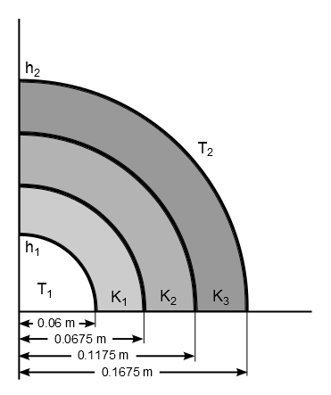
A pipe carrying steam at 230 °C has an internal diameter of 0.12 m and a thickness of 0.0075 m. The thermal conductivity of the pipe material, K1, is 49 W/m⋅K and the convective heat transfer coefficient on the inside, h1, is 85 W/m2K. The pipe is insulated by two layers of insulation, one with 0.05 m thickness with thermal conductivity, K2, of 0.15 W/m⋅K and over it another layer with 0.05 m thickness with thermal conductivity, K3, of 0.48 W/m⋅K. The outside is exposed to air at 35 °C with a convection coefficient, h2, of 18 W/m2K. Determine the interface temperatures at locations x = 0.06 m, 0.0675 m, 0.1175 m, and 0.1675 m.
| Material Properties | Geometric Properties | Loading |
|---|---|---|
|
Thermal conductivity of pipe material, K1 = 49 W/m⋅K Thermal conductivity of the 1st insulation layer, K2 = 0.15 W/m⋅K Thermal conductivity of the 2nd insulation layer, K3 = 0.48 W/m⋅K |
Internal radius of the pipe = 0.06 m Thickness of the pipe = 0.0075 m Thickness of the 1st insulation layer = 0.05 m Thickness of the 2nd insulation layer = 0.05 m |
Bulk temperature at pipe inner radius, T1 = 230 °C Convective film coefficient at pipe inner radius, h1 = 85 W/m2K Bulk temperature at the outside radius of the 2nd insulation layer, T2 = 35 °C Convective film coefficient at the outer radius of the 2nd insulation layer, h2 = 18 W/m2K |
Analysis Assumptions and Modeling Notes
The problem is solved for three cases with a hollow cylinder using 3D 8-node thermal solid elements (SOLID278) for case 1, 3D 20-node thermal solid elements (SOLID279) for case 2, and with 3D 10-node thermal solid elements (SOLID291) for case 3.
The pipe and the insulation layers are modeled as separate volumes. The bulk temperatures and convective film coefficients at the inside radius of the pipe and the outside radius of the second insulation layer are defined via SFE,,,CONV for cases 1 and 2, and SF,,CONV for case 3.
A steady-state (static) thermal analysis is then performed to determine the interface temperature at various locations.
Results Comparison
| Target (°C) | Mechanical APDL (°C) | Ratio | |
|---|---|---|---|
| Temperatures at the interface (SOLID278) | |||
| X = 0.06 m | 222.300 | 222.236 | 1.000 |
| X = 0.0675 m | 222.200 | 222.141 | 1.000 |
| X = 0.1175 m | 77.040 | 76.207 | 0.989 |
| X = 0.1675 m | 48.030 | 50.068 | 1.042 |
| Temperatures at the interface (SOLID279) | |||
| X = 0.06 m | 222.300 | 222.258 | 1.000 |
| X = 0.0675 m | 222.200 | 222.163 | 1.000 |
| X = 0.1175 m | 77.040 | 76.508 | 0.993 |
| X = 0.1675 m | 48.030 | 50.133 | 1.044 |
| Temperatures at the interface (SOLID291) | |||
| X = 0.06 m | 222.300 | 222.298 | 1.000 |
| X = 0.0675 m | 222.200 | 222.203 | 1.000 |
| X = 0.1175 m | 77.040 | 77.042 | 1.000 |
| X = 0.1675 m | 48.030 | 48.028 | 1.000 |