


VM279
VM279
T-Stress for a Crack in a Plate Using the CINT Command
Overview
Test Case
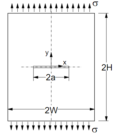
A rectangular plate with a center crack is subjected to an end tensile stress σ as shown in Figure 279.1. Symmetry boundary conditions are considered and T-Stress is determined using the CINT command.
| Material Properties | Geometric Properties | Loading | |||||
|---|---|---|---|---|---|---|---|
|
| Tensile stress (σ) = 100 MPa |
Analysis Assumptions and Modeling Notes
The problem is solved using a 2D PLANE183 element with plane strain element behavior and 3D solid elements (SOLID185 and SOLID186). A one-quarter plate is modeled and symmetry boundary conditions are considered. The crack tip nodes and the number of paths surrounding the crack tip nodes are defined using the CINT command. The plate is subjected to a tensile stress and the T-Stress is computed for the crack tip nodes. In the 3D analysis, a plane strain condition is achieved by constraining UZ degrees of freedom of all nodes (displacement in the Z-direction). The crack front and the path surrounding the crack front are defined using the CINT command.