VM267
VM267
Inclined Crack in 2D Plate Under Uniform Tension Loading
Overview
| Reference: | T.L. Anderson, Fracture Mechanics: Fundamentals and applications, CRC Press, Boca Raton, FL, 1995. |
| Analysis Type(s): | Static Analysis (ANTYPE = 0) |
| Element Type(s): | 2D 4 node structural solid (PLANE182) |
| Input Listing: | vm267.dat |
|
VM267 requires a supplemental .cdb input file which is too long to include full input listings. This file must be present in your working directory for the test case to run properly. Additionally, the geometry and mesh should be regenerated. Download link: MAPDL Test Case Files for 2024 R2 vm267.cdb |
Test Case
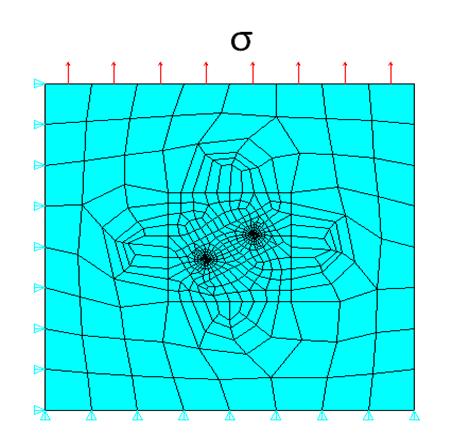
A 2D plate with length L is subjected to uniform tension loading. An inclined crack of length 2a is modeled with an angle of (30° - θ) between the crack surface and loading direction. Stress intensity factors are computed using the CINT,TYPE,SIFS command.

| Material Properties | Geometric Properties | Loading |
E = 210G Pa Nu = 0.3 | L = 0.3m Crack length 2a = 0.09m θ = 30° | σ = 10MPa |
Analysis Assumptions and Modeling Notes
The problem is solved using 2D PLANE182 element with plain strain element behavior (Figure 465: Finite element model of 2D inclined crack). The plate is constrained along X direction at X=0 and along Y direction at Y=0. The crack tip node components and the number of paths surrounding the crack tip are defined using CINT command. Mode 1 and Mode 2 stress intensity factors obtained from contours 2, 3, 4, and 5 are then averaged and compared against the reference solution.