


VM266
VM266
3D Crossing Beams in Contact with Friction
Overview
Test Case
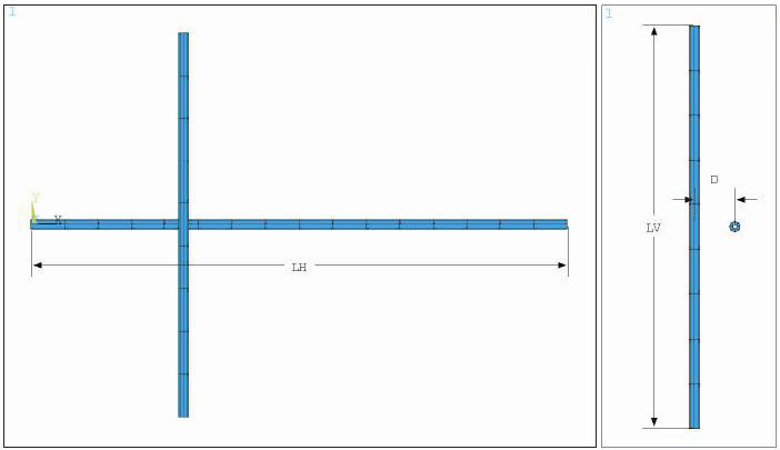
Two orthogonal beams with similar cross section and with an initial out-of-plane displacement are brought into contact by undergoing large displacements in 3D space. Normal and frictional contact forces are calculated at 0.5, 0.66, 0.83, and 1 second, and then compared against reference values.
| Material Properties | Geometric Properties | Loading |
|
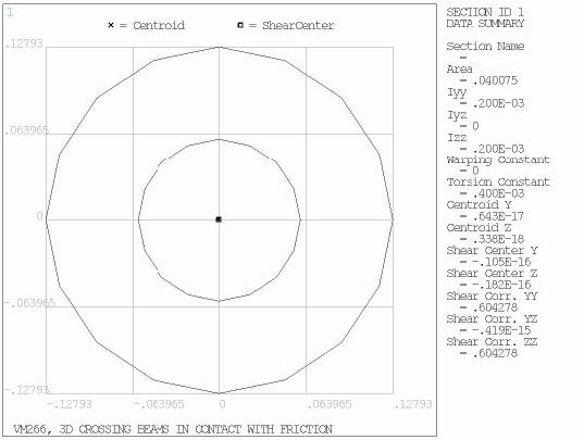
E=1.0 E+8 psi ν = 0.0 µ = 0.1 | LH=14 in LV=10 in D = 1 in Cross-Section properties: Ri = 0.06 in Ro = 0.12793 in A = 4.0 E-2 in2 Iyy = Izz =2.0 E-4 in4 |
Ux = 0.18 in Uz = 1.8 in |
Analysis Assumptions and Modeling Notes
The beams are modeled using quadratic shape functions, with 16 equal length elements for the horizontal beam and 9 equal length elements for the vertical beam. The vertical beam is clamped at both ends, and the horizontal beam has the left end free and is restrained in all DOF at the right end except for the translational and out of plane directions. Displacement loading is applied at the right end of the horizontal beam to bring both beams into contact. Target elements (TARGE170) are defined on the vertical beam, and contact elements (CONTA177) are defined on the horizontal beam with penalty algorithm. A friction coefficient of 0.1 and penalty values for normal and tangential contact of 1.0E+4 are chosen according to the reference data. The normal and frictional contact forces are then calculated at different time steps and compared against the reference.
The model is solved again using traction-based crossing-beam contact: KEYOPT (3) = 3. An area factor, A = 5.71425 is used to scale the traction-based contact definition from the force-based contact definition. It has units m-2 and is determined from the contact radius and element length (l): A = 1/(rl). This factor is used to scale the penalty values and results so that they use proper units.
Results Comparison
| Target | Mechanical APDL | Ratio | ||
|---|---|---|---|---|
| Normal Contact Force | NFORCE3 (t = 0.5s) | 17.000 | 17.177 | 1.010 |
| NFORCE4 (t = 0.66s) | 33.800 | 34.030 | 1.007 | |
| NFORCE5 (t = 0.83s) | 50.400 | 50.440 | 1.001 | |
| NFORCE6 ( t= 1s) | 67.000 | 66.295 | 0.989 | |
| Frictional Contact Force | TFORCE3 (t = 0.5s) | 1.700 | 1.717 | 1.010 |
| TFORCE4 (t = 0.66s) | 3.380 | 3.403 | 1.007 | |
| TFORCE5 (t = 0.83s) | 5.040 | 5.044 | 1.001 | |
| TFORCE6 ( t= 1s) | 6.700 | 6.629 | 0.989 | |
| Traction Based Contact – Normal Pressure | NPRES3 (t = 0.5s) | 97.1422 | 98.1578 | 1.010 |
| NPRES4 (t = 0.66s) | 193.1416 | 194.4582 | 1.008 | |
| NPRES5 (t = 0.83s) | 287.9982 | 288.2287 | 1.001 | |
| NPRES6 ( t= 1s) | 382.8547 | 378.8312 | 0.989 | |
| Traction Based Contact - Frictional Pressure | TPRES3 (t = 0.5s) | 9.7142 | 9.8158 | 1.010 |
| TPRES4 (t = 0.66s) | 19.3142 | 19.4458 | 1.008 | |
| TPRES5 (t = 0.83s) | 28.7998 | 28.8229 | 1.001 | |
| TPRES6 ( t= 1s) | 38.2855 | 37.8831 | 0.989 | |