


VM257
VM257
Transient Analysis of a Swing with Two Rigid Links and
Beam
Overview
Test Case
The swing shown in Figure 436: Swing Consisting of Two Rigid Links and a Beam with Mid-Span Mass consists of
a long aluminum beam of rectangular cross-section (width = 1mm, depth
= 5 mm) and a mid-span mass (mass = 0.5 kg). The modulus of elasticity,
Poisson’s ratio and density of aluminum are shown in the table
below. The mass is rigidly connected to the beam at its mid-span position,
labeled C in the figure. The beam is suspended at each end by two
rigid links, and is initially at rest in the position as shown in
the Figure 436: Swing Consisting of Two Rigid Links and a Beam with Mid-Span Mass. The rigid links impose a kinematic
constraint corresponding to fixed distance between points O1 and A,
and O2 and E of 0.36 and
 respectively. The
points B and D indicate the quarter and three quarter span points
of the beam, respectively. The loading of the system consists of a
triangular pulse in the
respectively. The
points B and D indicate the quarter and three quarter span points
of the beam, respectively. The loading of the system consists of a
triangular pulse in the
 direction applied at
the mid-span mass. This pulse starts at time t = 0 s, reaches a peak
value of 2N at t =0.128 s and goes back to zero at t = 0.256 s, as
shown in Figure 437: Triangular-Pulse Loading.
direction applied at
the mid-span mass. This pulse starts at time t = 0 s, reaches a peak
value of 2N at t =0.128 s and goes back to zero at t = 0.256 s, as
shown in Figure 437: Triangular-Pulse Loading.


| Material Properties | Geometric Properties | Loading | |||||||||
|---|---|---|---|---|---|---|---|---|---|---|---|
|
|
|

Analysis Assumptions and Modeling Notes
The system is modeled with four equal length BEAM188 beam elements, two rigid links and a rigid mass. The dynamic response of the system was calculated over a period of 1 s using HHT method with 30% numerical damping and auto time stepping turned on with a minimum of 1000 time steps.
The system was solved twice. In the first case, the rigid links were modeled using MPC184 rigid links and in the second case the rigid links were modeled as rigid bodies using TARGE170 elements. Similar results were obtained in both analyses.
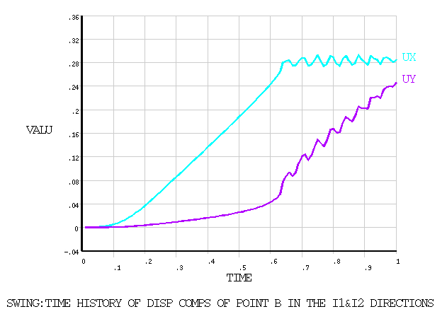
Figure 438: Predicted Time Histories for Displacement Components of Point
B shows the predicted time histories
for the
 and
and
 direction displacement components of point
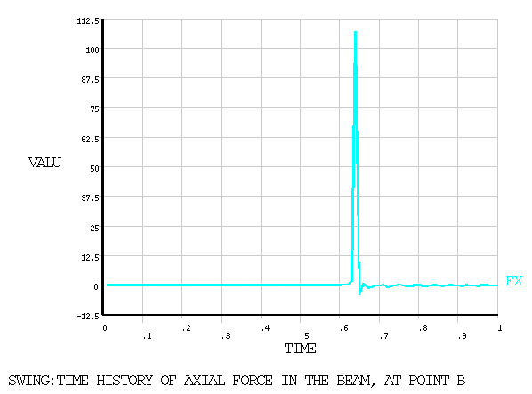
B and Figure 439: Calculated Time History of Axial Force at Point B shows the calculated time histories
of the axial force at point B. These figures should be compared to
Figures 15 and 16 respectively in the reference.
direction displacement components of point
B and Figure 439: Calculated Time History of Axial Force at Point B shows the calculated time histories
of the axial force at point B. These figures should be compared to
Figures 15 and 16 respectively in the reference.
Results Comparison
| Target | Mechanical APDL | Ratio | |
|---|---|---|---|
| Results using MPC184 rigid links | |||
| TIME (sec) | 0.6410 | 0.6400 | 0.998 |
| DISP-UY (m) | 0.2800 | 0.2807 | 1.003 |
| DISP-UX (m) | 0.0750 | 0.0783 | 1.043 |
| FORCE-FX (N) | 112.7000 | 107.2069 | 0.951 |
| Results using TARGE170 rigid links | |||
| TIME (sec) | 0.6410 | 0.6400 | 0.998 |
| DISP-UY (m) | 0.2800 | 0.2807 | 1.003 |
| DISP-UX (m) | 0.0750 | 0.0783 | 1.043 |
| FORCE-FX (N) | 112.7000 | 107.1904 | 0.951 |