VM256
VM256
Evaluation of Fracture Parameters for a Center Crack in a Plate
Overview
| Reference: | W.F.Brown, Jr., J.E.Srawley, Plane strain crack toughness testing of high strength metallic materials, ASTM STP-410, (1966). |
| Analysis Type(s): | Static analysis (ANTYPE = 0) |
| Element Type(s): |
2D 8-Node Structural Solid Element (PLANE183) 3D Structural Solid Element (SOLID185) 3D Structural Solid or Layered Solid Element (SOLID186) |
| Input Listing: | vm256.dat |
|
VM256 requires a supplemental .cdb input file which is too long to include full input listings. This file must be downloaded and placed in your working directory for the test case to run properly. Additionally, the geometry and mesh should be regenerated. Download link: MAPDL Test Case Files for 2024 R2 vm256-1.cdb vm256-2.cdb vm256-3.cdb |
Test Case
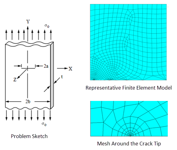
A long plate with a center crack is subjected to a pressure applied on the top and bottom as shown in the problem sketch. Symmetry boundary conditions are considered and the following fracture parameters are determined via the CINT command: KI, J-integral, material force, and T-stress.
| Material Properties | Geometric Properties | Loading | |||||||
|---|---|---|---|---|---|---|---|---|---|
|
|
|
Analysis Assumptions and Modeling Notes
The problem is first solved using the 2D PLANE183 element with plane-strain element behavior. A one-quarter plate is modeled and symmetry boundary conditions are considered. The crack-tip nodes and the number of paths surrounding the crack are defined via the CINT command. The plate is subjected to pressure and the fracture parameters are calculated for the crack-tip nodes.
In the 3D analysis using SOLID185 and SOLID186 elements, respectively, a plane-strain condition is achieved by constraining the UZ degrees of freedom of all nodes (displacement in the Z-direction). The crack front and the path surrounding the crack front are defined via the CINT command. The fracture mechanics parameters KI, J-integral, material force, and T-stress are then calculated in POST1.
Results Comparison
| Target | Mechanical APDL | Ratio | |
|---|---|---|---|
| Using PLANE183 Elements (2D Analysis) | |||
| Stress intensity KI | 1.0000 | 1.0022 | 1.002 |
| J-integral | 0.3030E-07 | 0.3025E-07 | 0.998 |
| Material force | 0.3030E-07 | 0.3025E-07 | 0.998 |
| T-stress | -0.5640 | -0.5668 | 1.005 |
| Using SOLID185 Elements (3D Analysis) | |||
| Stress intensity KI | 1.0000 | 1.0006 | 1.001 |
| J-integral | 0.3030E-07 | 0.3001E-07 | 0.990 |
| Material force | 0.3030E-07 | 0.3001E-07 | 0.990 |
| T-stress | -0.5640 | -0.5923 | 1.050 |
| Using SOLID186 Elements - Surface Crack (3D Analysis) | |||
| Stress intensity KI | 1.0000 | 1.0030 | 1.003 |
| J-integral | 0.3030E-07 | 0.3044E-07 | 1.005 |
| Material force | 0.3030E-07 | 0.3044E-07 | 1.005 |
| T-stress | -0.5640 | -0.5665 | 1.004 |


