


VM258
VM258
Spin-up Maneuver of a Flexible Beam
Overview
Test Case
The problem shown in Figure 440: Spin-up Maneuver Problem Model consists of a flexible beam characterized by a nonlinear generalized stress-generalized strain relationship. The material properties used to define the nonlinear general beam section are shown in the table below. The beam is pinned at one end and the other end is free, and is initially at rest.
| Beam Section Properties |
|---|
| Axial Stiffness: AE = 2.8e7 |
| Bending Stiffness in xz Plane : I1 E = 1.4e4 |
| Bending Stiffness in xy Plane: I2 E = 1.4e4 |
| Torsional Stiffness: JG =1.4e4 |
| Transverse Shear Stiffness in xz Plane: A1 G =1.0e7 |
| Transverse Shear Stiffness in xy Plane: A2 G =1.0e7 |
| Mass density: Aρ = 1.2 kg/m |
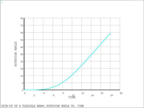
The loading of the system consists of a prescribed rotation about the z-axis (normal to the plane) applied at the pinned end. The rotation varies with time as follows:

During transient analysis, the inertial/gyroscopic effects cause
the beam to bend during the acceleration phase (0
 t
t
 15s) and stretch
due to the centrifugal force during the steady-state motion at constant
angular velocity (t > 15s). The prescribed rotation angle vs.
time is shown in Figure 441: Rotation Angle Versus Time.
15s) and stretch
due to the centrifugal force during the steady-state motion at constant
angular velocity (t > 15s). The prescribed rotation angle vs.
time is shown in Figure 441: Rotation Angle Versus Time.

Analysis Assumptions and Modeling Notes
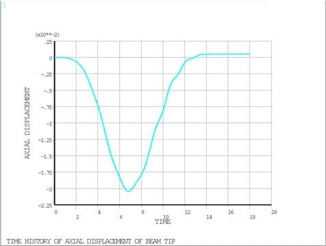
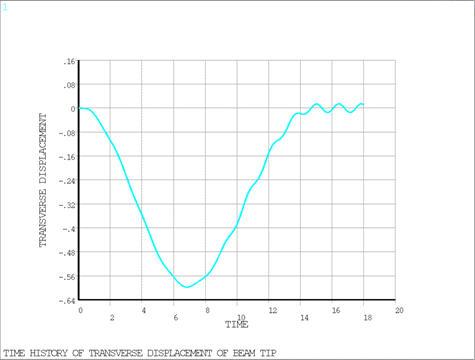
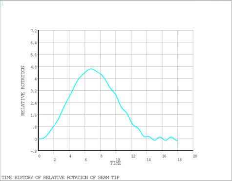
The system is modeled with four equal length BEAM189 beam elements and two MPC 184 elements: a general joint element that spans the length of the beam and a revolute grounded joint element at the pinned end. The joint elements are used to get the output of nodal displacements in a coordinate system that rotates with the beam. The dynamic response of the system was calculated over a period of 18 s using the HHT time integration method with 10% numerical damping. Auto time stepping is used with midstep residual check and an initial time step size of 0.005s. Figure 442: Predicted Time History for Axial Displacement of Beam Tip, Figure 443: Predicted Time History for Transverse Displacement of Beam Tip, and Figure 444: Predicted Time History for Rotation of Beam Tip Relative to Base show the predicted time histories for the axial and transverse displacements of the beam tip and rotation of the beam tip relative to the base. These figures should be compared to Figure 6 in the reference.
Results Comparison
In the tables below are presented comparisons of the peak values of Mechanical APDL results together with the times at which they occur to the corresponding reference values and their times.
Note: The expected values (Target) used in the following tables were extracted from the reference graphs (see Figure 6 in the reference) and cannot be considered precise values.
| Target | Mechanical APDL | Ratio | |
|---|---|---|---|
| Peak Axial Displacement | |||
| TIME (sec) | 6.7 | 6.8256 | 1.019 |
| TIP DISP-UX | -0.0190 | -0.0204 | 1.076 |
| Peak Transverse Displacement | |||
| TIME (sec) | 6.85 | 6.8256 | 0.996 |
| TIP DISP-UY | -0.5750 | -0.5976 | 1.039 |
| Peak Relative Rotation | |||
| TIME (sec) | 6.7 | 6.7856 | 1.013 |
| RELATIVE ROTATION-ROTZ (degrees) | 4.4240 | 4.6269 | 1.046 |
| Steady-state Stretch | |||
| TIME (sec) | 16 | 17.5475 | 1.097 |
| TIP STRETCH-UX | 5 x 10⁻⁴ | 5 x 10⁻⁴ | 1.003 |