


VM248
VM248
Delamination Analysis of Double Cantilever Beam
Overview
| Reference: | G. Alfano and M. A. CrisfieldFinite Element Interface Models for the Delamination Analysis of Laminated Composites: Mechanical and Computational Issues, International Journal for Numerical Methods in Engineering, Vol. 50, pp. 1701-1736 (2001). | ||||||||||
| Analysis Type(s): | Static analysis (ANTYPE = 0) | ||||||||||
| Element Type(s): |
| ||||||||||
| Input Listing: | vm248.dat |
Test Case
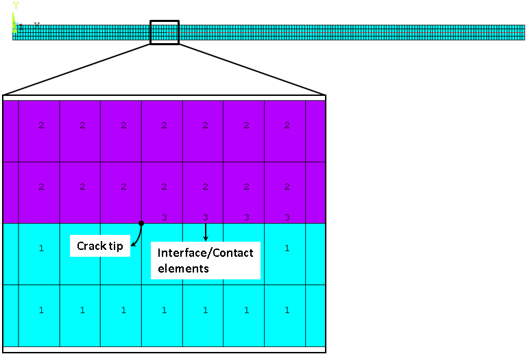
A double cantilever beam of length l, width w and height h with an initial crack of length a at the free end is subjected to a maximum vertical displacement Umax at top and bottom free end nodes. Determine the vertical reaction at point P based on the vertical displacement for the interface model.

| Material Properties | Geometric Properties | Loading | |||||||||||||
|---|---|---|---|---|---|---|---|---|---|---|---|---|---|---|---|
|
|
| |||||||||||||
| |||||||||||||||
Analysis Assumptions and Modeling Notes
Static analysis is performed using regular meshes of 4 x 200 4-node INTER202 elements with PLANE182 elements, 2 x 200 6-node INTER203 elements with PLANE183 elements, 2 x 200 8-node INTER205 elements with SOLID185 elements, 4 x 200 2-node CONTA172 elements with PLANE182 elements, 2 x 200 3-node CONTA172 elements with PLANE183 elements, and 2 x 200 4-node CONTA174 elements with SOLID185 elements. In the 3D model, all the UZ degrees of freedom are constrained to make it behave like a 2D model. An imposed displacement of Uy = 10 mm acts at the top and bottom free nodes. Equivalent material constants of C1 = 25, C2 = 0.004 and C3 = 1000 are used for the interface material, as Mechanical APDL uses the exponential form of the cohesive zone model and the reference uses a bilinear constitutive model.
Results Comparison
| INTER202 | |||
|---|---|---|---|
| Target | Mechanical APDL | Ratio | |
| Max RFORCE and corresponding DISP: | |||
| RFORCE FY (N) | 60.00 | 60.069 | 1.001 |
| DISP UY(mm) | 1.00 | 1.000 | 1.000 |
| End RFORCE and corresponding DISP: | |||
| RFORCE FY (N) | 24.00 | 24.294 | 1.012 |
| DISP UY(mm) | 10.00 | 10.00 | 1.00 |
| INTER203 | |||
|---|---|---|---|
| Target | Mechanical APDL | Ratio | |
| Max RFORCE and corresponding DISP: | |||
| RFORCE FY (N) | 60.00 | 60.063 | 1.001 |
| DISP UY(mm) | 1.00 | 1.000 | 1.000 |
| End RFORCE and corresponding DISP: | |||
| RFORCE FY (N) | 24.00 | 24.299 | 1.012 |
| DISP UY(mm) | 10.00 | 10.00 | 1.00 |
| INTER205 | |||
|---|---|---|---|
| Target | Mechanical APDL | Ratio | |
| Max RFORCE and corresponding DISP: | |||
| RFORCE FY (N) | 60.00 | 60.086 | 1.001 |
| DISP UY(mm) | 1.00 | 1.000 | 1.000 |
| End RFORCE and corresponding DISP: | |||
| RFORCE FY (N) | 24.00 | 24.281 | 1.012 |
| DISP UY(mm) | 10.00 | 10.00 | 1.00 |
| CONTA172 (dropped midside nodes) | |||
|---|---|---|---|
| Target | Mechanical APDL | Ratio | |
| Max RFORCE and corresponding DISP: | |||
| RFORCE FY (N) | 60.00 | 60.094 | 1.002 |
| DISP UY(mm) | 1.00 | 1.000 | 1.000 |
| End RFORCE and corresponding DISP: | |||
| RFORCE FY (N) | 24.00 | 24.296 | 1.012 |
| DISP UY(mm) | 10.00 | 10.00 | 1.00 |
| CONTA172 | |||
|---|---|---|---|
| Target | Mechanical APDL | Ratio | |
| Max RFORCE and corresponding DISP: | |||
| RFORCE FY (N) | 60.00 | 60.088 | 1.001 |
| DISP UY(mm) | 1.00 | 1.000 | 1.000 |
| End RFORCE and corresponding DISP: | |||
| RFORCE FY (N) | 24.00 | 24.301 | 1.013 |
| DISP UY(mm) | 10.00 | 10.00 | 1.00 |
| CONTA174 (dropped midside nodes) | |||
|---|---|---|---|
| Target | Mechanical APDL | Ratio | |
| Max RFORCE and corresponding DISP: | |||
| RFORCE FY (N) | 60.00 | 60.110 | 1.002 |
| DISP UY(mm) | 1.00 | 1.000 | 1.000 |
| End RFORCE and corresponding DISP: | |||
| RFORCE FY (N) | 24.00 | 24.283 | 1.012 |
| DISP UY(mm) | 10.00 | 10.00 | 1.00 |