


VM247
VM247
Campbell Diagrams and Critical Speeds Using Symmetric
Bearings
Overview
Test Case
A rotor-bearing system is analyzed to determine the whirl speeds. The distributed rotor was modeled as a configuration of six elements with each element composed of subelements. See Table 10: Geometric Data of Rotor-Bearing Elements for a list of the geometrical data of the elements. Two undamped linear bearings were located at positions four and six. Modal analysis is performed on rotor bearing system with multiple load steps to determine the critical speeds and Campbell values for the system.
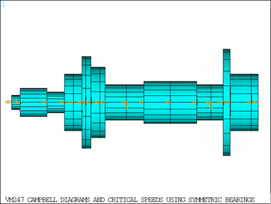
Table 10: Geometric Data of Rotor-Bearing Elements
| Element No. | Subelement No. | Axial Distance to Subelement (cm) | Inner Diameter (cm) | Outer Diameter (cm) |
|---|---|---|---|---|
| 1 | 1 | 0.00 | 0.51 | |
| 2 | 1.27 | 1.02 | ||
| 2 | 1 | 5.08 | 0.76 | |
| 2 | 7.62 | 2.03 | ||
| 3 | 1 | 8.89 | 2.03 | |
| 2 | 10.16 | 3.30 | ||
| 3 | 10.67 | 1.52 | 3.30 | |
| 4 | 11.43 | 1.78 | 2.54 | |
| 5 | 12.70 | 2.54 | ||
| 6 | 13.46 | 1.27 | ||
| 4 | 1 | 16.51 | 1.27 | |
| 2 | 19.05 | 1.52 | ||
| 5 | 1 | 22.86 | 1.52 | |
| 2 | 26.67 | 1.27 | ||
| 6 | 1 | 28.70 | 1.27 | |
| 2 | 30.48 | 3.81 | ||
| 3 | 31.50 | 2.03 | ||
| 4 | 34.54 | 1.52 | 203 |
| Material Properties | Geometric Properties | Loading | |||||||||||||||
|---|---|---|---|---|---|---|---|---|---|---|---|---|---|---|---|---|---|
|
|
Analysis Assumptions and Modeling Notes
A modal analysis is performed on a rotor bearing system with QR Damp method to determine the whirl speeds and Campbell values. The rotor shaft is modeled with BEAM188 elements with quadratic shape function and an internal node to enhance element accuracy. MASS21 element is used to model the rigid disk (concentrated mass) and COMBIN14 element is used to model symmetric bearings. No shear effect is included in the rotor-bearing system. The displacement along X as well as the rotation around X axis is constrained so that the rotor bearing system does not have any torsion or traction related displacements. The CORIOLIS command is activated in a stationary reference frame to apply gyroscopic effect to the rotating structure. The whirl speeds for slope (excitation per revolution) 1 and 4 are determined and compared with the numerical solution.
Note: In the "Results Comparison" table below, the values listed from the reference article are the whirl speeds (frequencies) and not the critical speeds. Also, the definition of the ratio differs between the reference article and this application. In the article, the whirl ratio equals the rotational velocity divided by the frequency. In this application, the ratio is the slope, which is equal to the frequency divided by the rotational velocity. As a result, the values listed in the reference article for a whirl ratio of 1/4 (see the "Results Comparison" table below) are divided by 4 so that they can be compared to the critical speeds obtained from this application with a slope of 4.
Results Comparison
| Target | Mechanical APDL | Ratio | |
|---|---|---|---|
| Whirl speeds for slope = 1 (rpm) | |||
| Mode 1 | 15470.0000 | 15478.5247 | 1.001 |
| Mode 2 | 17159.0000 | 17128.0842 | 0.998 |
| Mode 3 | 46612.0000 | 46711.5585 | 1.002 |
| Mode 4 | 49983.0000 | 50093.9640 | 1.002 |
| Mode 5 | 64752.0000 | 64875.3791 | 1.002 |
| Mode 6 | 96547.0000 | 95636.2738 | 0.991 |
| Whirl speeds for slope = 4 (rpm) | |||
| Mode 1 | 4015.0000 | 4013.3857 | 1.000 |
| Mode 2 | 4120.2500 | 4116.1717 | 0.999 |
| Mode 3 | 11989.2500 | 12015.4449 | 1.002 |
| Mode 4 | 12200.0000 | 12227.0010 | 1.002 |
| Mode 5 | 18184.2500 | 18205.2845 | 1.001 |
| Mode 6 | 20162.2500 | 20127.0570 | 0.998 |