The 2D and 3D transducer models are created in Ansys DesignModeler and meshed in the Ansys Mechanical application. The major axis length is 450 mm and the minor axis length is 210 mm.
The 2D transducer is meshed with PLANE223 coupled-field (piezoelectric) elements with dropped midside nodes for the piezoelectric ceramics. PLANE182 structural elements are used for the aluminum shell and rubber boot.
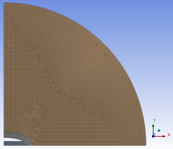
The surrounding water is a circular region meshed with FLUID29 acoustic elements with a distance of 1.1 m. The truncated boundary defined by the 1.1 m circular arc is meshed with FLUID129 infinite fluid elements to absorb outgoing acoustic waves.
The following figure shows the final mesh with an average element size of 10 mm:
The 3D transducer’s ceramic stacks are modeled with SOLID226 coupled-field (piezoelectric) elements with dropped midside nodes. The aluminum shell and rubber boot are modeled with SOLID185 structural elements.
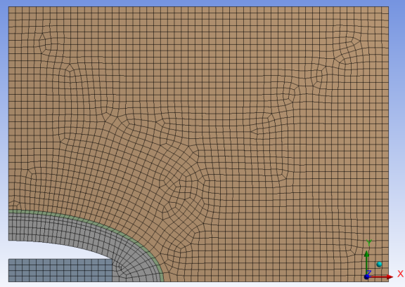
A rectangular region 300 mm from the sides of the transducer represents the surrounding water. The model is extruded 10 mm in the out-of-plane (z axis) direction to create a 2.5-D representation.
The following figure shows the final mesh with an average element size of 10 mm: