The following models for the wind turbine blade are described:
23.3.1. Wind Turbine Blade: BEAM188 Models
Following is the general process for modeling the wind turbine blade using beam elements:
Create the geometry models of the representative blade cross sections.
For this problem, the geometry was created using DesignModeler.
The root part is contained within the first two round sections (the area between sections #1 and #2). The root part is made of the skin material only.
Two sections (sections #3 and #4) are defined at the same location. While section #4 and the remaining sections consist of all three section components (skin, spar caps, and shear webs), section #3 contains only the skin component. Because sections #2 and #3 are topologically consistent, a transition part is defined between sections #2 and #3, connecting the root part to the airfoil part.
The airfoil part starts at section #4 and ends at section #9.
Mesh the section-area geometry.
The section-area geometry is meshed using MESH200 elements in a quadrilateral shape with eight nodes (KEYOPT(1) = 7), and appropriate material property types are assigned to different components within the sections.
The section meshes are output to external files (SECWRITE).
The following example input stores the mesh information for section #1:
CMSEL, s, area1            ! Select area component of first blade cross-section.
ALLSEL, below, area        ! Select everything below the selected area
SECWRITE, mesh1,sect,,1		! Output mesh to file "mesh1.sect"
Define constant beam sections types(BEAM), each with a meshed subtype (MESH).
Beam sections with a mesh subtype are defined (SECTYPE), and the section meshes from the prior step are restored (SECREAD).
The following example input reads the mesh information contained in the mesh1.sect file and associates it with beam section #1:
SECTYPE,1,beam,mesh        ! Specify beam section 1 with mesh subtype
SECREAD,mesh1,sect,,mesh   ! Import mesh from file "mesh1.sect"
Define seven tapered-beam section types (TAPER).
Using the constant previously defined beam sections, define seven beam sections (SECTYPE) of section type TAPER.
The sections are assigned later to beam elements in the various blade parts (root, transition, and airfoil).
The following example input defines section #11 for the transition part:
SECTYPE,11,taper           ! Specify tapered-beam section type
SECDATA,2,2.0              ! Put BEAM section 2 at global X location 2.0 as the starting section
SECDATA,3,4.0              ! Put BEAM section 3 at global X location 4.0 as the ending section
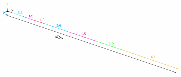
Create a line diagram of the blade model.
Following is a line diagram of the blade model:
Line segments end where the constant beam sections are defined so that no elements are split by the sections.
Generate both beam meshes.
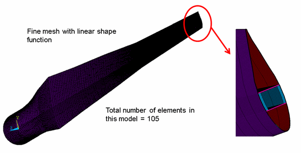
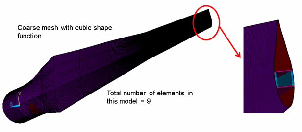
Two BEAM188 meshes are generated, one a fine mesh with the linear interpolation option (KEYOPT(3) = 0), the other a coarse mesh with the cubic interpolation option (KEYOPT(3) = 3). The following two figures show both models, respectively:
The elements are visualized with the expanded solid display option (/ESHAPE) to show the 3D section details.
The following example input meshes line #3, representing the transition part:
SECNUM,11          ! Set the current section as section 12
LMESH,3            ! Mesh line number 3
23.3.2. Wind Turbine Blade: SHELL281 Reference Model
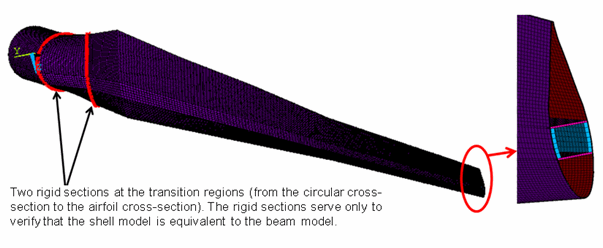
To generate a reference solution, an equivalent 3D model is created using SHELL281 elements, as shown in the following figure:
Material properties and boundary conditions in this model are identical to those of the BEAM188 models.


