Boundary conditions for the beam and the reference shell models are given separately, as follows:
23.5.1. BEAM188 Blade Model Boundary Conditions
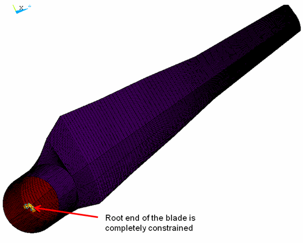
For the beam models, the root end of the blade is completely constrained, as shown in the following figure:
23.5.2. SHELL281 Blade Model Boundary Conditions
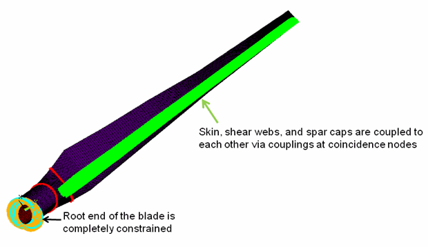
For the reference shell model, the root end of the blade is also completely constrained, as shown in this figure:
Extensive constraint equations (CEs) are used for properly assembling the three structural components (indicated by the green areas in the figure above).
As a result of the simplified model, an abrupt section-property change exists from the three-component airfoil section to the skin-only transition section. Significant section deformation is expected at this connection location.
While the SHELL281 reference model can simulate the section deformation, the same capability in the BEAM188 models is greatly limited due to basic beam characteristics. To create a comparable reference model, an artificially rigid plane is inserted at this location, indicated by the red symbols in the figure above. Similarly, another rigid plane is inserted at the connection of the root part and the transition part.
This technique does not invalidate the beam modeling, as these types of sudden section-property changes do not exist in actual blade designs.


