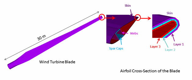
The following figure shows a model of a single turbine blade with a length of 30 meters, consisting of three primary structural components (the skin, the spar caps, and the shear webs):
In an actual application, all three components of the blade can be made using layered composites. For illustrative purposes, this problem adopts a three-layered construction for the skin only, with homogeneous and orthotropic materials used for the spar caps and shear webs.
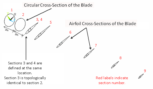
The blade geometry is defined via representative cross-sections at eight locations along the longitudinal axis, as shown in this figure:
The geometry is assumed to be linearly tapered between each pair of adjacent cross-sections. The natural frequencies and modes of the blade are analyzed using three comparative models:


