


A nonlinear static analysis is performed in two load steps of one second each. The analysis diverges in the first load step, rezoning occurs, and the analysis resumes.
Restart files are saved at each substep, as rezoning requires a restart file, and the substep at which rezoning is required is still unknown. Results items are also stored at each substep.
For illustration only, this example problem saves restart files and results items at all substeps, despite the considerable memory requirements for doing so. In most cases, however, it is sufficient to save them at every few substeps instead. |
The following input applies the solution settings for the run:
Example 27.5: Applying the Solution Settings for the Run
/solu
time,1                      ! Define time for first load step
nlgeom,on                   ! Enable nonlinear geometry effects
OUTRES,ALL,ALL              ! Save the results data for each substep
RESCONTRL,DEFINE,ALL,ALL,0  ! Save restart files for each substep
NSUBST,100,1000000,20       ! Define initial, maximum and minimum substeps
solve                       ! Solve the first load step
The initial run diverges in the first load step at TIME = .7718. The following figure shows the deformed shape of the model at the last converged substep:
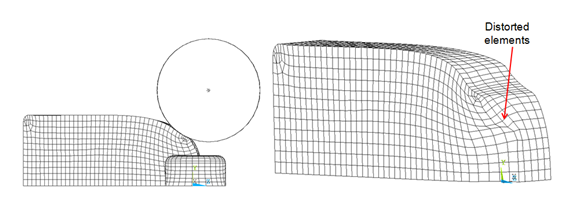
Element shape checking of the deformed model suggests that the mesh is overly distorted at the location indicated.
Rezoning repairs the distorted mesh and allows the analysis to continue. Rezoning is applied to this problem as described in the following topics:
The best substep at which to initiate rezoning is determined by examining the deformed model and the physics of the simulation.
The analysis diverges after the 40th substep at TIME = .7718. Very little time (from TIME = .77 to .7718) occurs between the 31st to the 40th substeps, however, indicating that severe distortion of the mesh begins to occur at the 31st substep.
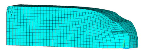
Because rezoning should be attempted at one or more substeps before the substep where mesh deformation occurs, the 30th substep is a logical choice at which to initiate rezoning. Shape-checking (SHPP or CHECK) of the deformed mesh at the 30th substep confirms the choice, as the deformed mesh violates no error limits.
The following figure shows the deformed mesh at the 30th substep:
Various remeshing options are available for rezoning. Because this is a 3D problem, however, a new mesh is read in to replace the original, distorted mesh.
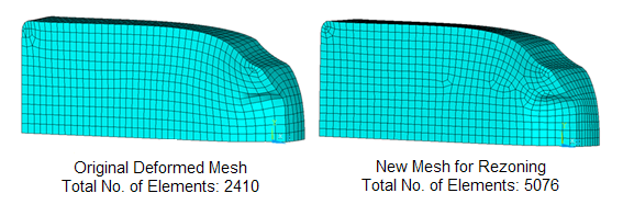
The new mesh can be generated in Workbench or by other third-party software by first creating the deformed geometry from the deformed mesh, then meshing the deformed geometry with new settings to obtain a new, good mesh. The new mesh must be better than the original mesh; otherwise, rezoning cannot improve convergence.
The following figure shows the original, deformed mesh and the new, good mesh:
Example 27.6: Initiating Rezoning at the 30th Substep and Reads in the New Mesh
/solu
rezone,manual,1,30            ! Start rezoning at the 30th substep
remesh,start                  ! Start “remeshing” process
remesh,read,Rezone_Mesh,cdb   ! Read new mesh in “cdb” format
remesh,finish                 ! Transfer boundary conditions and loadings from the
!                               old mesh to the new mesh, and recreate contact
!                               pairs (if any)
After remeshing (REMESH,FINISH), the program transfers surface loads, forces, boundary conditions, and contact pairs (if any) from the original, deformed old mesh to the new, good mesh. It is good practice to check the model after remeshing to verify that all such transfers to the new mesh were successful.
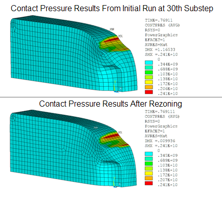
After remeshing, solution and results items from the original mesh are mapped to the new mesh, and the resulting residual forces are rebalanced (MAPSOLVE).
The following figure shows the contact pressure results for the top roller contact pair, first from the 30th substep (where rezoning is performed), and after mapping variables and balance residuals from the original mesh to the new mesh:
The mapping operation concludes the rezoning process, and a standard multiframe restart resumes solution processing using the new mesh.
After mapping quantities from the old to the new mesh and rebalancing the residual forces, a multiframe restart (ANTYPE,,RESTART,,,CONTINUE) resumes the nonlinear solution with the new mesh.
The following input restarts the analysis:
Example 27.8: Restarting the Analysis
/clear,nostart
/file,Hot_Rolling_Model    ! Specify same job name as initial run
/solu
antype,,restart            ! Specify analysis type (restart)
solve                      ! Solve first load step

! Load Step2: Rotate rollers
time,2                     ! Define time for second load step
esel,s,ename,,185
allsel,below,element       ! Select the nodes of the block
ddel,all,uz                ! Free the block to move in Z direction
allsel,all
nsel,s,,,9999
d,all,rotx,-6.28           ! Rotate top roller
nsel,s,,,20999
d,all,roty,-10.47          ! Rotate side roller
allsel,all
mp,mu,1,0.6                ! Use high value of friction
OUTRES,ALL,10              ! Save results items at every 10th substep
RESCONTRL,DEFINE,ALL,30,0  ! Save restart files at every 30th substep
NSUBST,1000,100000,20
solve                      ! Solve second load step