


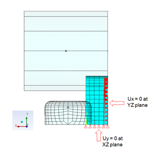
Symmetric boundary conditions are applied on both symmetry planes of the block, as shown in the following figure:
To showcase the usefulness of rezoning in 3D problems, this problem is solved statically in two load steps:
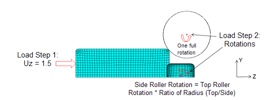
The block is allowed to move towards the rollers and establish contact with them. The displacement (Uz = 1.5 m) is applied on the left end face of the block, as shown in the following figure:
Both the rigid rollers (top and side) are constrained in all directions with the use of pilot nodes. No friction is used.
Example 27.3: Applying the Boundary Conditions and Loading Used in the First Load Step
! Load Step 1
! Boundary Conditions
cmsel,s,ux_node           ! Select node on symmetry plane (YZ plane)
d,all,ux                  ! Apply symmetry boundary conditions
cmsel,s,uy_node           ! Select node on symmetry plane (XZ plane)
d,all,uy                  ! Apply symmetry boundary conditions
d,9999,all                ! Constrain top roller in all degrees of freedom
d,20999,all               ! Constrain side roller in all degrees of freedom
allsel,all
! Loadings
cmsel,s,uz_node           ! Select the nodes of the left end face of the block
d,all,uz,1.5              ! Apply prescribed displacement (Uz =1.5m)
mp,mu,1,0                 ! Use zero value of friction
Hot-rolling occurs in this load step. The rollers are allowed to rotate, and the block is free to move in the Z direction. A high value of friction (µ = 0.6) is used.
Because the top and side rollers are different sizes, different rotations are given to the rollers in order to maintain continuity. Based on the size of top roller, the friction coefficient, and the block length, one full rotation is applied to the top roller (as shown in Figure 27.8: Loadings).
No forward or backward slip is considered while calculating the rotation value of the side roller. Rotation of the side roller is calculated using this formula:
Rotation of side roller = Rotation of top roller * (Radius of top roller / Radius of side roller)
Example 27.4: Applying the Boundary Conditions and Loading Used in the Second Load Step
! Load Step 2
cmsel,s,uz_node         ! Select the nodes of the left end face of the block
ddel,all,uz             ! Free the block to move in Z direction
nsel,s,,,9999
d,all,rotx,-6.28        ! Rotate top roller
nsel,s,,,20999
d,all,roty,-10.47       ! Rotate side roller
mp,mu,1,0.6             ! Use high value of friction
allsel,all