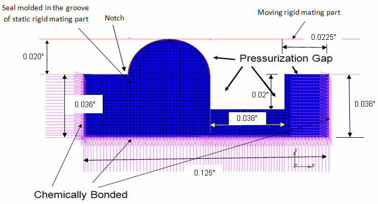
The following static elastomeric seal assembly is considered for analysis:
The following requirements and physical behaviors are considered in the finite-element model and solution procedure for this problem:
The coefficient of friction (between the bead and the mating surface) is not critical for static seals.
The coefficient is therefore not modeled here.
A fluid pressure of 4000 psi is applied.
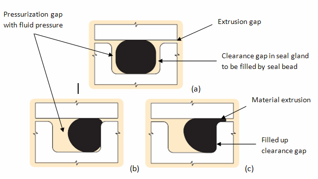
The pressure improves seal integrity, but can also create extrusions of the bead. The extrusions are due to shear stresses (caused by differential axial pressure created by the fluid, as an extrusion gap is provided).
As fluid pressure increases, sealing capacity improves but bead extrusion can occur.
The fluid pressure on the seal surfaces tends to compress the seal axially, forcing the deformed bead further into the gland therefore improving contact. As the fluid pressure increases, the seal's internal shear stresses also increase slowly, driving the seal material into the extrusion gap.
The degree and severity of the extrusion depends on the operating pressures, operating temperatures, geometry of the clearance gap, and seal shape and material.
It is of critical importance for the model to predict any bead extrusion.
This type of extrusion typically causes nibbling damage [1] to the seal, caused by large tensile stresses close to the free surface of the extruded material.
The following figure illustrates the progression of seal deformation, showing the seal gland being filled and the corresponding bead extrusion as fluid pressure is applied:
The action of the seal assembly and functional loads on the seal can cause large deformations and strains, in turn causing severe mesh distortions and leading to convergence failure in the nonlinear analysis. In such situations, rezoning can repair the mesh, map results from the old (distorted) mesh to the new mesh, and allow the analysis to continue.
Convergence failure caused by material or geometric instability cannot be remedied by rezoning.
Rezoning can occur on the entire domain or on specific regions within the domain.
If one or more regions are selected for rezoning at the same time during the analysis, the process is called horizontal rezoning.
If one or more rezoning operations are performed at different times during the analysis, the process is called vertical rezoning.
Following are the general steps in the rezoning process:
Within a given load step, select the substep at which rezoning should be initiated.
Select the region(s) to be rezoned.
Remesh the selected region(s), replacing the old (distorted) mesh with a new mesh.
After remeshing has occurred, boundary conditions and loading from the old mesh are mapped to the new mesh.
Map state variables from the old mesh to the new mesh.
This step establishes equilibrium in the new mesh by balancing residual forces.
Continue the analysis with the new mesh via a restart.
During the remeshing phase of a rezoning operation, a new mesh is created in the distorted geometry and replaces the old mesh.
Remeshing can occur by reading in a generated mesh or a generic third-party mesh (CDB file), or by using element-splitting refinement of selected regions of the distorted mesh.
In this example, remeshing via the element-splitting method is used because splitting increases the number of degrees of freedom in a given region without changing mesh topology. This remeshing method is especially useful for modeling material flow through confined cavities (the primary physical behavior of hyperelastic seals).
With element splitting, the mesh topology does not change in the interior of the selected regions where elements are simply split evenly. In the transition region between the refined (new mesh) and the old mesh, however, layers of transition of elements are generated, changing the mesh topology in these regions. The transitions can be all quadrilateral or can be composed of degenerate quadrilaterals.
Typically, an all-quadrilateral transition requires more than one element layer to create a compatible mesh between the split and unsplit regions. The degenerate elements can do the same in just one element layer; however, a degenerate element transition is more prone to locking than a quadrilateral element transition zone.


