


This section describes the following analyses performed for this problem:
For procedure and solution controls for the modal cyclic symmetry analysis and nonlinear prestessed modal cyclic symmetry analysis with linear perturbation, refer to Analysis and Solution Controls for the Centrifugal Impeller Analysis Using Cyclic Symmetry and Linear Perturbation.
For general information about linear perturbation, see Linear Perturbation Analysis in the Structural Analysis Guide.
In a tuned analysis, which is an idealization of the real structure, all the blades are considered to be identical in terms of blade properties (for example, stiffness).
To perform a nonlinear prestressed mode-superposition harmonic cyclic symmetry analysis with linear perturbation, you must first prestress the structure with nonlinear effects in a static solution. The perturbed procedure is used to perform a modal analysis from the prestressed state, followed by a mode-superposition harmonic analysis.
For this analysis, the EO = 2 engine order excitation is applied using the
CYCFREQ command with Option = EO
and Value1 = 2.
The frequency range of excitation, 513.76 - 538.76 Hz with 50 substeps is chosen based on the modal frequencies for the mode-superposition harmonic analysis. With this frequency range, the first few modes of the bladed disk are excited.
The following example input shows the steps in this analysis:
/solu

csys,0
antype,static              ! Perform Static analysis
nlgeom,on                  ! Include large deformation effects
rescontrol,define,all,1    ! Enable the file writing in multiframe restart
nsub,10,10,10              ! Number of substeps = 10

allsel,all,all
nsle
bf,all,temp,50             ! Define temperature = 50
allsel,all,all

csys,1
cgomega, 0, 0, 1680,       ! Centrifugal load


time,1.0

solve
finish

/solu
antype,static,restart,,,perturb   ! Perform a static restart with perturb from the last ! substep of the previous static solve
perturb,modal,,,DZEROKEEP         ! Set the analysis options for perturbed modal analysis
solve,elform

modopt,lanb,50,0,14000
mxpand,,,,yes,,yes

cycopt,hindex,2,2,2
/input,'mapped_on_cyclic_model',dat   ! Apply mapped pressure data to generate a
                                      ! load vector
solve
fini

/solu
antype,harmonic
hropt,msup,,,yes                      ! MSUP Harmonic, Write modal coordinates
outres,all,all

harfrq,513.76,538.76
nsubs,50,50,50

cycfreq,eo,2                          ! EO = 2

/com, Zeroing Prestressed loads
thexpand,off
cgom, 0, 0, 0
sfedele,all,all,all

lvscale,1,1                           ! Scale the load vector
kbc,1

dmpstr,0.01                           ! Structural damping

solve
finish
In a mistuned response analysis, which is a realistic case, deviations in blade properties such as stiffness are considered.
To perform this analysis with linear perturbation, the procedure is identical to
the one described in Nonlinear Prestressed Mode-Superposition Harmonic Cyclic Symmetry Analysis with
Linear Perturbation - Tuned Response, except that
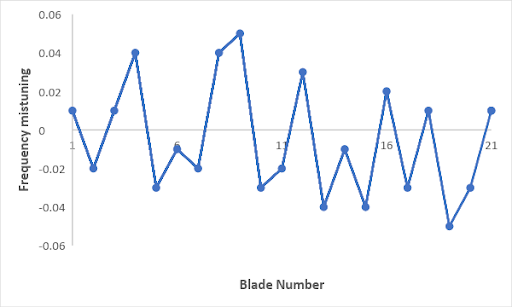
mistuning parameters are defined. These mistuning parameters are specified as an
array input using the CYCFREQ command with
Option = MIST. For this analysis, the following
mistuning profile is considered:
An EO = 2 engine order excitation is applied using the CYCFREQ
command with Option = EO and
Value1 = 2.
The cyclic mode-superposition harmonic analysis with mistuning requires a CMS
reduction on the blade alone. For this, you need to provide the blade information
using the CYCFREQ command with Option
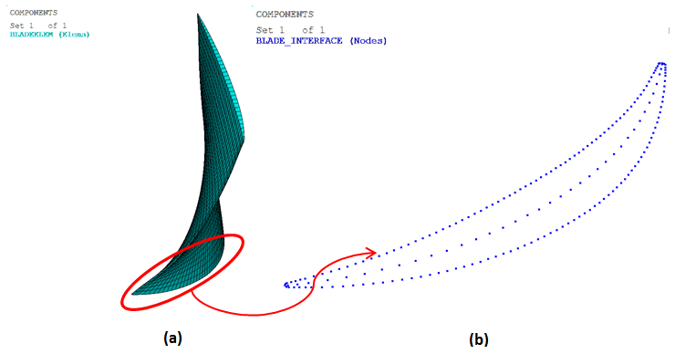
= BLADE. This blade information is composed of the name of the nodal component
containing the blade boundary nodes at the blade-to-disk interface, the name of the
element component containing the blade elements, and the number of blade modes to
include in the CMS reduction.
The following figure shows the element component of the fan blade and the blade boundary nodes at the blade-to-disk interface:
Figure 45.13: (a) Element Component of Fan Blade; (b) Blade Boundary Nodes at the Blade-to-Disk Interface
To determine modal frequencies and corresponding modal damping ratios, damped
modal analyses for tuned and mistuned models are performed on the reduced systems
via CYCFREQ with Option = MODAL, and
Value1 = ON.
For the forced-response with aerodamping and mistuning, a frequency range of excitation of 503.76 - 553.76 Hz (with 50 substeps) is considered.
The following example input shows the different steps in this analysis:
!-----------------------------------------------
! DAMPLED MODAL SOLVE (MISTUNED)
!-----------------------------------------------
/output,scratch

/solu
antype,harm
hropt,msup
thexpand,off     ! Ignore thermal strains

kbc,1
harfrq,503.76,553.76
nsubst,50,50,50
dmpstr,0.01	! Structural damping

/com, Prestressed loads
thexpand,off
cgomga, 0, 0, 0
fdele,all,all
sfedele,all,all,all

outres,all,all
hrout,on
lvscale,1,1

cycfreq,default
cycfreq,eo,2
cycfreq,blade,blade_interface,BladeElem,2

*dim,kmist,array,22,1
kmist(1,1) = 0.01,-0.02,0.01,0.04,-0.03,-0.01,-0.02,0.04,0.05
kmist(10,1) = -0.03,-0.02,0.03,-0.04,-0.01,-0.04,0.02,-0.03,0.01,
kmist(19,1) = -0.05,-0.03,0.01,0.01
cycfreq,mist,k,kmist
cycfreq,aero,fileAeroArray
cycfreq,modal,on,100,500,600

allsel,all
/output
solve
/output,scratch
fini

/output
!-----------------------------------------------
! CYCLIC MSUP HARMONIC SOLVE
!-----------------------------------------------
/output,scratch

/solu
antype,harm
hropt,msup
thexpand,off      ! Ignore thermal strains

kbc,1
harfrq,503.76,553.76
nsubst,50,50,50
dmpstr,0.01       ! Structural damping

/com, Prestressed loads
thexpand,off
cgomga, 0, 0, 0
fdele,all,all
sfedele,all,all,all

outres,all,all
hrout,on
lvscale,1,1

cycfreq,default
cycfreq,eo,2
cycfreq,blade,blade_interface,BladeElem,2
cycfreq,mist,k,kmist
cycfreq,aero,fileAeroArray

allsel,all
solve
Note: For an ideal/tuned cyclic bladed disk, engine order excitation will excite only those modes with a number of nodal diameters that match the harmonic index of the excitation. For a mistuned bladed disk, the modes have multiple harmonic contents so that many modes will be excited by engine order excitation.