Due to the symmetry of the structure, only half of the rubber boot is modeled. For the rubber boot, the hyperelastic material model is used. The shaft is considered as a rigid body.
Modeling for this problem involves the following tasks:
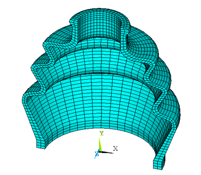
The 3D model is generated by using the rubber boot seal profile. SOLID185 elements are used to model the actual 3D structure of the rubber boot as shown in the figure below. This model has 3387 elements.
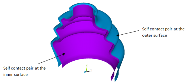
Three contact pairs are defined to simulate contact occurring in the rubber boot during the shaft movement:
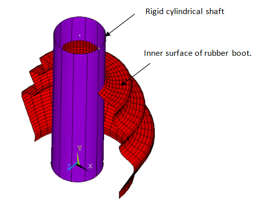
Rigid flexible contact between the rigid cylindrical shaft and the inner surface of the rubber boot.
Self contact at the inner surface of the rubber boot using the surface-projection-based contact method.
Self contact at the outer surface of the rubber boot using the surface-projection-based contact method.
The rigid cylindrical shaft is modeled by the TARGE170 element with the TSHAP,CYLI command. The radius of the cylindrical shaft is 14 mm. This rigid cylinder is in initial interference with the internal surface of the rubber boot.
The following contact settings are used for the contact elements, CONTA174:
KEYOPT(9) = 2 to include interference with ramped effects
KEYOPT(4) = 0 to set the location of the contact detection point at the gauss integration point
KEYOPT(10) = 2 to update contact stiffness at each iteration
The following commands illustrate the contact settings of the rigid flexible contact pair:
et,2,170              ! Target element to define rigid cylinder
et,3,174              ! Contact element for rigid-flexible contact pair
keyopt,3,9,2          ! Include interference with ramped effects
keyopt,3,4,0          ! Gauss point contact detection algorithm
keyopt,3,10,2         ! Update contact stiffness at each iteration
r,2
rmodif,2,1,14         ! Radius of the cylinder = 14 mm
rmodif,2,3,1.0
To model a self contacting pair, both the target and contact surfaces are the same. KEYOPT(4) = 3 is used to define surface-projection-based contact, and KEYOPT(10) = 2 is used to update contact stiffness at each iteration.