


The general procedure for creating a cross section consists of the following steps:
Define the section and associate a section ID number with the section.
Define the geometry data for the section.
The following commands are available for creating, viewing, and listing cross sections, and for managing cross-section libraries:
Table 13.1: Cross-Section Commands
| Command | Purpose |
|---|---|
| SECTYPE | Associates section with
SECID (section number) |
| SECDATA | Defines section geometry data |
| SECCONTROL | Overrides program calculated properties. |
| SECFUNCTION | Specifies shell section thickness as a tabular function. |
| SECNUM | Identifies the SECID
(section number) to be assigned to an element |
| SECOFFSET | Defines section offset for shell cross sections |
| SECPLOT | Plots geometry of a shell section to scale |
| SLIST | Summarizes section properties |
| SDELETE | Deletes a cross section |
For complete documentation of the cross-section commands, see the Command Reference.
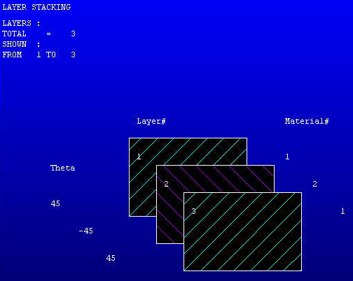
Figure 13.1: Plot of a Shell Section shows the layer stacking of a shell section. The layer order, along with material and orientation of each layer, is represented here:
Use the SECTYPE command to define a section and associate it with a section ID number. For example, the following command assigns a section identification number (2) to a shell section:
Use the SECDATA command to define the layers of a shell section. Each consecutive SECDATA command defines the next layer's thickness, material, orientation, and number of integration points. (The number of integration points input on SECDATA is not used by thermal shell elements.) The layer orientation angle is the angle between the layer coordinate system and the x-axis of the element coordinate system.
You may designate the number of integration points (1, 3, 5, 7, or 9) located thru the thickness of each layer. When only 1, the point is always located midway between the top and bottom surfaces. If 3 or more points, 2 points are located on the top and bottom surfaces respectively and the remaining points are distributed equal distance between the 2 points. An exception occurs when designating 5 points, where the quarter point locations are moved 5 percent toward their nearest layer surface to agree with the locations selected with real constant input. The default for each layer is 3.
If a shell section has only one layer, and the number of section integration points is equal to one, then the shell does not have any bending stiffness. This may result in solver difficulties, and may affect convergence adversely.
Use the SECCONTROL command to override the program calculated section properties. By default, the program calculates shear correction factors and mass for each element based on the input section geometry and material properties. Any values input on the SECCONTROL command will replace the defaults. (SECCONTROL does not apply to thermal shell elements.)
Use the SECFUNCTION command to associate a tabular thickness variation with the section. A table that describes thickness with respect to the global Cartesian coordinate system may be associated with a shell section. This thickness is interpreted as the total thickness of a shell. The total thickness of a layered shell, and all layer thickness values, will be scaled according to the tabular function.
Use the SECNUM command to associate an element with a particular section. Any element created after the SECNUM command will have this section identification number (2) as its section attribute.
Use the AATT command to associate an area with a shell section type. When the area is meshed, the new elements are associated with the section specified on the AATT command. The section specified by the SECNUM command is ignored.
The SECTYPE, SECDATA, SECOFFSET, SECFUNCTION, and SECCONTROL commands () are all associated with the ShellTool in the GUI.
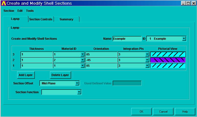
The top part of the Layup page of the ShellTool relates a section ID number to a Shell section type (and, optionally, a section name) (SECTYPE). The middle part of the page of the ShellTool defines each layer in the positive Z direction of the element (SECDATA). Note that the order of the rows in the spreadsheet ascends up the page, resembling that stacking of the layers. (Integration point data for each layer is ignored by thermal shell elements.) The bottom contains the fields for section offset information, if needed (SECOFFSET). You can define tapered shells by specifying a section function relating thickness to global coordinates (SECFUNCTION).
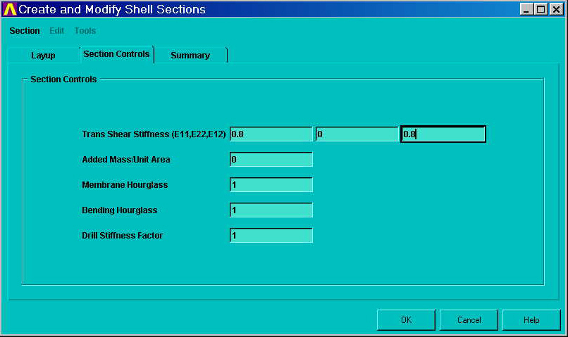
The transverse shear stiffness, hourglass coefficients and drill stiffness of the sections are calculated from the section geometry and material properties. The default added mass per unit area of the section is always zero. On the Section Controls page, you can override the program calculated quantities (SECCONTROL). (The Section Controls page does not apply to thermal shell elements.)
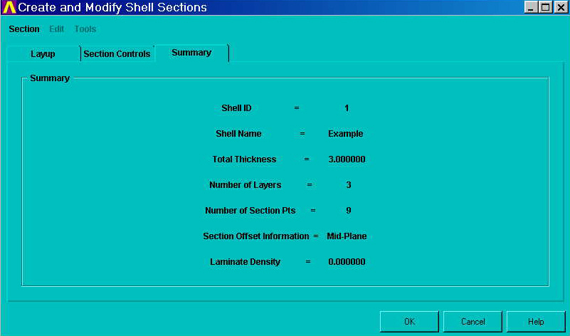
On the Summary page, you can review the section properties.
Cross-section data for shell sections can be stored in cross-section libraries. To create standard cross sections for later use, create one or more cross sections, edit the Jobname.log file, and copy the appropriate SECCONTROL, SECDATA, SECFUNCTION, SECOFFSET, and SECTYPE commands into a separate file with a SECT extension.