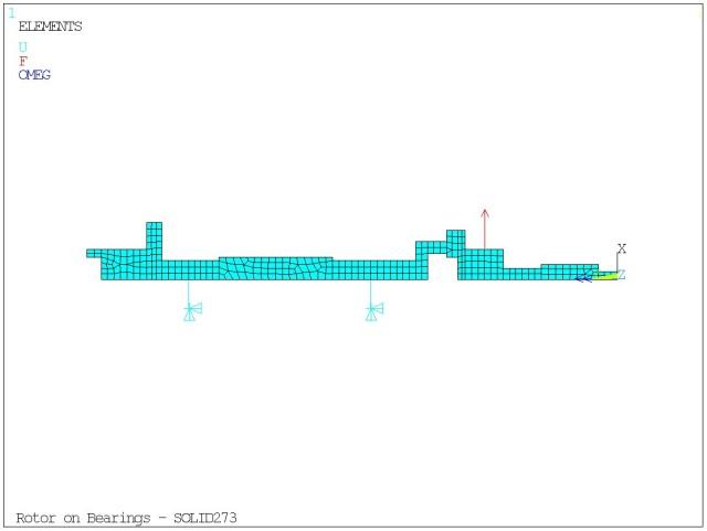
The model is depicted in Figure 7.3: Rotating Shaft. The shaft is rotating at 105000 RPM and is supported by two bearings. It is excited by an impulse along the X axis at a node situated in the right overhung part of the rotor.
The specifications for this model, including the geometry, and the stiffness characteristics for the identical bearings are found in VM247, "Campbell Diagrams and Critical Speeds Using Symmetric Bearings" in the Mechanical APDL Verification Manual.
/PREP7

MP,EX,1,2.078e+11
MP,DENS,1,7806
MP,NUXY,1,0.3

et,1,273,,3      !! 3 circumferential nodes
nbdiam = 18
*dim,diam,array,nbdiam
diam(1) = 1.02e-2
diam(2) = 2.04e-2
diam(3) = 1.52e-2
diam(4) = 4.06e-2
diam(5) = diam(4)
diam(6) = 6.6e-2
diam(7) = diam(6)
diam(8) = 5.08e-2
diam(9) = diam(8)
diam(10) = 2.54e-2
diam(11) = diam(10)
diam(12) = 3.04e-2
diam(13) = diam(12)
diam(14) = 2.54e-2
diam(15) = diam(14)
diam(16) = 7.62e-2
diam(17) = 4.06e-2
diam(18) = diam(17)

k,1
k,2 ,diam(1)/2
k,3 ,diam(1)/2,1.27e-2
k,4 ,         ,1.27e-2
a,1,2,3,4

k,5 ,diam(2)/2,1.27e-2
k,6 ,diam(2)/2,5.08e-2
k,7 ,diam(3)/2,5.08e-2
k,8 ,         ,5.08e-2
a,4,3,5,6,7,8

k,9 ,diam(3)/2,7.62e-2
k,10,         ,7.62e-2
a,8,7,9,10

k,11,diam(4)/2,7.62e-2
k,12,diam(4)/2,8.89e-2
k,13,         ,8.89e-2
a,10,9,11,12,13

k,14,diam(5)/2,10.16e-2
k,15,         ,10.16e-2
a,13,12,14,15

k,16,diam(6)/2,10.16e-2
k,17,diam(6)/2,10.67e-2
k,18,3.04e-2/2,10.67e-2
k,19,         ,10.67e-2
a,15,14,16,17,18,19

k,20,diam(7)/2,11.43e-2
k,21,diam(8)/2,11.43e-2
k,22,3.56e-2/2,11.43e-2
k,23,3.04e-2/2,11.43e-2
a,18,17,20,21,22,23

k,24,diam(8)/2,12.7e-2
k,25,3.56e-2/2,12.7e-2
a,22,21,24,25

k,26,         ,12.7e-2
k,27,diam(9)/2,13.46e-2
k,28,diam(10)/2,13.46e-2
k,29,          ,13.46e-2
a,26,25,24,27,28,29

k,30,diam(10)/2,16.51e-2
k,31,          ,16.51e-2
a,29,28,30,31

k,32,diam(11)/2,19.05e-2
k,33,          ,19.05e-2
a,31,30,32,33

k,34,diam(12)/2,19.05e-2
k,35,diam(12)/2,22.86e-2
k,36,          ,22.86e-2
a,33,32,34,35,36

k,37,diam(13)/2,26.67e-2
k,38,diam(14)/2,26.67e-2
k,39,          ,26.67e-2
a,36,35,37,38,39

k,40,diam(14)/2,28.7e-2
k,41,          ,28.7e-2
a,39,38,40,41

k,42,diam(15)/2,30.48e-2
k,43,          ,30.48e-2
a,41,40,42,43

k,44,diam(16)/2,30.48e-2
k,45,diam(16)/2,31.5e-2
k,46,diam(17)/2,31.5e-2
k,47,          ,31.5e-2
a,43,42,44,45,46,47

k,48,diam(17)/2,34.54e-2
k,49,3.04e-2/2,34.54e-2
k,50,         ,34.54e-2
a,47,46,48,49,50

k,51,diam(18)/2,35.5e-2
k,52,3.04e-2/2,35.5e-2
a,49,48,51,52

esize,0.5e-2
amesh,all

sect,1,axis    !! symmetry axis along Y
secd,1, 0,0,0, 0,1,0
naxi

! bearings
et,3,combin14
keyopt,3,2,1
et,4,combin14
keyopt,4,2,2
et,5,combin14
keyopt,5,2,3
r,3,4.378e+7

visu = -0.02	!! visualization of bearing
n,10000,visu,16.51e-2
n,10001,visu,28.7e-2

type,3
real,3
e,node(0,16.51e-2,0),10000
e,node(0,28.7e-2,0),10001
type,4
real,3
e,node(0,16.51e-2,0),10000
e,node(0,28.7e-2,0),10001
type,5
real,3
e,node(0,16.51e-2,0),10000
e,node(0,28.7e-2,0),10001

d,10000,all
d,10001,all

fini

! *** modal analysis in rotation
pi = acos(-1)
spin = 105000*pi/30

/solu
antype,modal
modopt,qrdamp,10,1.0
coriolis,on,,,on
betad,1.e-5
omega,,spin
mxpand,10,,,yes
solve
fini

! *** mode-superposition transient analysis
dt = 1.0e-04
nodF = node(0.20300E-01,0.88900E-01,0)

/solu
antype,transient
trnopt,msup,10
deltim,dt
kbc,0
outres,all,none
outres,nsol,all
outres,rsol,all

f,nodF,FX,0
time,2*dt
solve

f,nodF,FX,1.e+3
time,10*dt
solve

f,nodF,FX,0
time,100*dt
solve
fini

! *** expansion pass
/solu
expass,on
numexp,all
solve
fini

! *** generate bearing reaction forces plot
/post26
rforce,2,10000,F,X,fxRightBearing
rforce,3,10000,F,Z,fzRightBearing
rforce,4,10001,F,X,fxLeftBearing
rforce,5,10001,F,Z,fzLeftBearing

/show,JPEG
plvar,2,3,4,5
EXTREME,2,5,1
/show,CLOSE
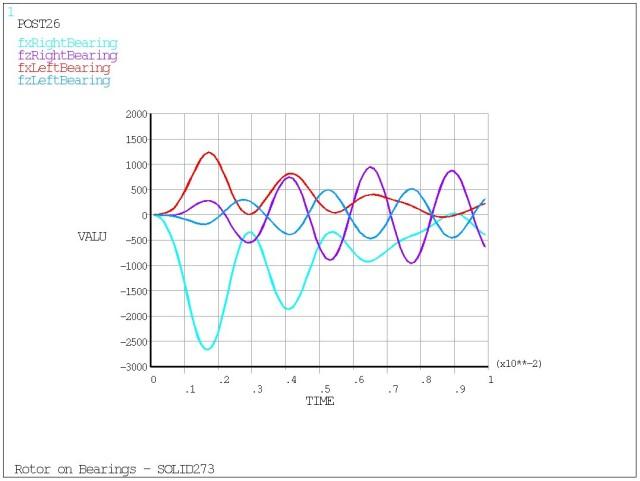
The plot of Bearing Reaction Forces vs. Time is shown in Figure 7.4: Rotating Shaft Output.


