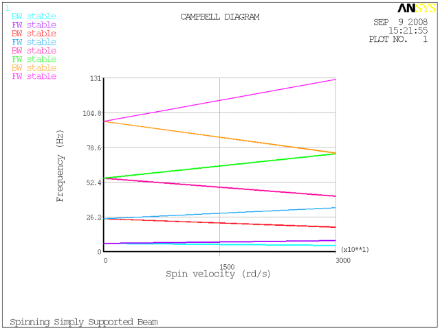
This example demonstrates a modal analysis of a rotating structure using a stationary reference frame. The analysis generates a Campbell diagram (PLCAMP).
These additional Campbell diagram examples are available in the Mechanical APDL Verification Manual:
For the Campbell diagram and critical speed analysis of a rotor on bearings, see VM247 "Campbell Diagrams and Critical Speeds Using Symmetric Bearings" and VM254 "Campbell Diagrams and Critical Speeds Using Symmetric Orthotropic Bearings".
For the Campbell diagram and stability analysis of a rotating beam on bearings with viscous internal damping, see VM261 "Rotating Beam with Internal Viscous Damping".
The geometric properties for this analysis are as follows:
| Length: 8m |
| Diameter: 0.2m |
The material properties for this analysis are as follows:
| Young's modulus (E) = 2e+11 N/m2 |
| Poisson's ratio (υ) = 0.3 |
| Density = 7800 kg/m3 |
Use this input file to perform the example modal analysis of a rotating structure using a stationary reference frame.
/batch,list
/title, Spinning Simply Supported Beam
!* Parameters
lx=8                  ! length
dia=0.2               ! diameter
/PREP7                ! -----
ET,1,16
R,1, dia, dia/2
MP,EX,1,2e+11
MP,DENS,1,7800
MP,PRXY,1,0.3
n,1
n,9,lx
fill,1,9
e,1,2
egen,8,1,-1
d,1,uy,,, ,,uz        ! simply supported left end
d,9,uy,,, ,,uz        ! simply supported right end
d,all,ux              ! supress axial motion
d,all,rotx            ! supress torsion
finish
/SOLU                 ! -----
antype,modal
! Use the QRDAMP eigensolver, request 8 modes,
!   get complex eigensolutions
modopt,qrdamp,8,,,on
! Reuse the block Lanczos eigenvectors from the first loadstep
qrdopt,on
! Write 8 modes to the result file, calculate
!   element results
mxpand,8,,,yes
! Apply Coriolis effect and specify
!   stationary reference frame
coriolis,on,,,on
! Solve 2 loadsteps with rotational velocity
omega,0.
solve
omega,30000.
solve
finish
/POST1                ! -----
! Plot Campbell Diagram
plcamp
! Print Campbell Diagram
prcamp
finish
The following table describes the input listing and the general process involved in the example analysis in more detail:
| Step | Description | APDL Command(s) |
|---|---|---|
| 1. | Set parameters. |
lx=8 dia=0.2 |
| 2. | Define nodes, elements, and material properties. |
ET,… R,… MP,... N,… E,… |
| 3. | Set boundary conditions. |
D,... |
| 4. | Set the analysis type (modal in this case). Use the QRDAMP eigensolver, request 8 modes, and specify complex eigensolutions. |
ANTYPE,MODAL MODOPT,QRDAMP,8,,,ON MXPAND,... |
| 5. | Include the Coriolis effect in a stationary reference frame. |
CORIOLIS,ON,,,ON |
| 6. | For each load step, define the rotation velocity, and then solve. |
OMEGA,… |
| 7. | Plot and print the Campbell diagram. |
The results of your analysis should be similar to those shown here:

The printout (PRCAMP) should yield the following data:
 PRINT CAMPBELL DIAGRAM
    Sorting : ON
    X axis unit : rd/s


  ***** FREQUENCIES (Hz) FROM CAMPBELL (sorting on) *****


 Spin(rd/s)          0.000      30000.000

     1   BW          6.207          4.639
     2   FW          6.207          8.305
     3   BW         24.750         18.547
     4   FW         24.750         33.027
     5   BW         55.461         41.735
     6   FW         55.461         73.701
     7   BW         98.248         74.337
     8   FW         98.248        129.852


