


VM261
VM261
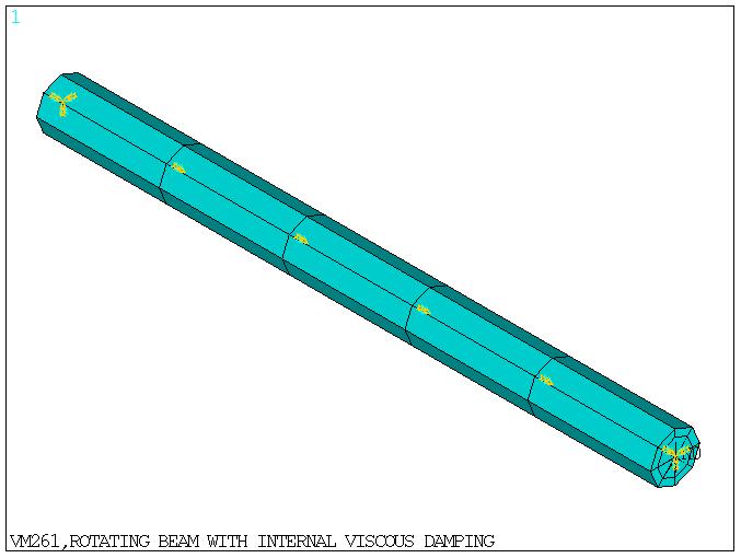
Rotating Beam with Internal Viscous Damping
Overview
Test Case
A beam with internal viscous damping is simply supported by means of two isotropic undamped bearings. Modal analysis is performed with multiple load steps to determine the critical speeds and logarithmic decrement of the system.
Material Properties | Geometric Properties | Loading |
Beam model E = 2.10E11 Pa GXY = 2.10E14 Pa DENS = 7800 Kg/m3 Nu = 0.3 Bearing stiffness Kyy = 1.75E+07 N/m Kzz = 1.75E+07 N/m | Beam length = 1.27m Beam diameter = 0.1016m | Rotational velocity 1st load step = 0 rpm 2nd load step = 1241.409 rpm 3rd load step = 2492.366 rpm 4th load step = 3743.324 rpm 5th load step = 5149.458 rpm 6th load step = 6245.240 rpm 7th load step = 7496.198 rpm 8th load step = 8747.156 rpm 9th load step = 9998.114 rpm 10th load step = 11249.071 rpm 11th load step = 12500.029 rpm 12th load step = 13789.184 rpm 13th load step = 14992.396 rpm |
Analysis Assumptions and Modeling Notes
The beam is modeled as an assembly of five equal length finite elements and meshed with BEAM188 elements. Internal viscous damping is included in the model as a material property using MP,BETD command. Modal analysis is performed using QR Damp eigensolver. Axial motion and rotation are suppressed to avoid any torsion or traction related displacements.
Separate element material attribute pointer is assigned to bearing elements to avoid material property of beam being carried over to the bearing elements. Gyroscopic damping and rotating damping are activated by using CORIOLIS command turned on in a stationary reference frame.
The critical speeds for a synchronous excitation (slope = 1) and logarithmic decrements of the first two unstable frequencies after first and second critical speeds are determined and compared against reference values of case1 (a). The logarithmic decrement values are obtained from Figure 3.
Results Comparison
| Target | Mechanical APDL | Ratio | |
|---|---|---|---|
| 1st forward critical speed (rpm) | 4950 | 5107.3538 | 1.032 |
| 2nd forward critical speed (rpm) | 10500 | 10693.6863 | 1.018 |
| Logarithmic decrement for 1st unstable frequency after critical speed | 0.0010 | 0.0010 | 0.989 |
| Logarithmic decrement for 2nd unstable frequency after critical speed | 0.0103 | 0.0099 | 0.964 |