


Global and local coordinate systems are used to locate geometry items. When you define a node or a keypoint, its coordinates are interpreted in the global Cartesian system by default. For some models, however, it may be more convenient to define the coordinates in a system other than global Cartesian. You can input the geometry in any of three predefined (global) coordinate systems, or in any number of user defined (local) coordinate systems.
A global coordinate system can be thought of as an absolute reference frame. Three predefined global systems are available: Cartesian, cylindrical, and spherical. All three of these systems are right-handed and, by definition, share the same origin. They are identified by their coordinate system (C.S.) numbers:
0 – Cartesian
1, 5, 6 – Cylindrical
2 – Spherical
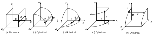
(a) Cartesian (X, Y, Z components) coordinate system 0 (C.S.0)
(b) Cylindrical (R, θ, Z components) coordinate system 1 (C.S.1)
(c) Spherical (R, θ, φ components) coordinate system 2 (C.S.2)
(d) Cylindrical (R, θ, Y components) coordinate system 5 (C.S.5)
(e) Cylindrical (R, θ, X components) coordinate system 6 (C.S.6)
In many cases, it may be necessary to establish your own coordinate system, whose origin is offset from the global origin, or whose orientation differs from that of the predefined global systems. (See Figure 3.2: Euler Rotation Angles for an example of a coordinate system defined by used for local, nodal, or working plane coordinate system rotations.) Such user defined coordinate systems, known as local coordinate systems, can be created in the following ways:
Use the LOCAL command to define the local system in terms of global Cartesian coordinates.
Use the CS command to define the local system in terms of existing nodes.
Use the CSKP command to define the local system in terms of existing keypoints.
Use the CSWPLA command to define the local system to be centered at the origin of the presently defined working plane.
Use the CLOCAL command to define the local system in terms of the active coordinate system with the command (see The Active Coordinate System).
When a local coordinate system is defined, it becomes the active coordinate system. As you create a local system, you assign it a C.S. identification number (which must be 11 or greater). You can create (or delete) local coordinate systems in any phase of your session. To delete a local system, use the CSDELE command.
To view the status of all global and local coordinate systems, use the CSLIST command.
Your local coordinate systems can be Cartesian, cylindrical, or spherical, similar in form to the three predefined global systems. Note that you may define local cylindrical and spherical coordinate systems in either circular or elliptical configuration. Additionally, you can define a toroidal local coordinate system, as illustrated in Figure 3.3: Coordinate System Types.
Note: Solid modeling operations in a toroidal coordinate system are not recommended. Areas or volumes generated may not be what you expect.
You may define as many coordinate systems as you like, but only one of these systems may be active at a time. The choice of active coordinate system is determined as follows: Initially, the global Cartesian system is active by default. Each time you define a local coordinate system, that newly-defined system then automatically becomes the active one. If you want to activate one of the global coordinate systems or some other previously defined coordinate system, use the CSYS command.
You can activate a coordinate system in any phase of your session. That same coordinate system will remain active in all subsequent phases until you change it explicitly.
Note: When you define a keypoint or a node, the program response labels the coordinates as X, Y, and Z, regardless of which coordinate system is active. You should make the appropriate mental substitutions if the active coordinate system is not Cartesian (R, θ, Z for cylindrical and R, θ, Φ for spherical or toroidal).
Specifying a constant value for a single coordinate implies a surface. For example, X = 3 represents the Y-Z plane (or surface) at X = 3 in a Cartesian system. Implied surfaces are used with various operations, such as selecting (xSEL commands) and moving (MOVE, KMOVE, etc.) entities. Some surfaces of constant value (C) are illustrated in the following figures. These surfaces may be located in either global or local coordinate systems to allow for any desired orientation. Note that for surfaces in elliptical coordinate systems, a constant R value (R = C) represents the value of R along the X-axis.
Open surfaces are assumed to be infinite. Cylindrical circular surfaces have a singularity at θ = ± 180°, as shown in Figure 3.6: Singularity Points, so that a fill generation of a string of nodes (FILL] or keypoints (KFILL] does not cross the 180° line. A fill operation defined from A to C will pass through B. A fill operation from A to D will pass through E. A fill operation from C to D will pass through B, A, and E.
For a specified cylindrical coordinate system, you can move the singularity point to θ = 0° (or 360°) so that a fill operation from C to D will not pass through B, A, or E. To move the singularity point, use the CSCIR command.
A similar singularity occurs in the toroidal coordinate system at Φ = ± 180° and can also be moved by the above methods. Singularities also occur in the spherical coordinate system at Φ = ± 90°, such that these locations should not be used.
Note that solid model lines will not be affected by these singularity locations. A curved line between two keypoints will take the shortest path in the angular direction, without regard to the location of the singularity point. (As a result, curved lines cannot span an arc of more than 180°.) Thus, in the figure above, circular lines from B to D or from D to B will pass through C.