


Porous media are materials containing pores. The materials are composed of solid-phase and open or closed pores. The solid portion is often called the skeleton. This documentation deals primarily with open pores filled with fluid (liquid or gas).
Many natural materials (such as rocks, soil and zeolites), biological materials (such as bones, tissue, wood and cork), and man-made materials (such as cements and ceramics) can be considered porous media. Pore structure geometry is inherently complicated. For engineering purposes, many of their important properties/characters can only be rationalized at a macroscopic scale by considering them to be porous media. Mechanics involving porous media must include mechanical response and fluid flow, requiring a coupled structural-pore-fluid-diffusion-thermal analysis.
The following porous-media topics are available:
- 4.12.1. Fluid Flow and Permeability
- 4.12.2. Porous Media Mechanics
- 4.12.3. Porous Media Material Properties
- 4.12.4. Heat-Transfer Properties
- 4.12.5. Thermal-Expansion Material Properties
- 4.12.6. Transient vs. Static Analysis
- 4.12.7. Partially Saturated Porous Media Flow and Coupled-Pore-Pressure-Thermal (CPT) Damping
Also see:
The flow of water or other liquid through porous media (such as soils) occurs when a difference in the water level exists, causing fluid pressure. Darcy's law defines porous media flow:
 | (4–86) |
where:
 = flow flux (Units: Length / Time) = flow flux (Units: Length / Time) |
 = relative permeability = relative permeability |
 = permeability = permeability |
 = degree of fluid saturation = degree of fluid saturation |
 = specific weight of fluid = specific weight of fluid |
 = pore pressure = pore pressure |
 = gradient operator (3D form shown) = gradient operator (3D form shown) |
 = gravity load direction (not to be confused with gravity
magnitude) = gravity load direction (not to be confused with gravity
magnitude) |
Permeability is a measure of the porous media's ability to allow fluids (gas or liquid) to flow through it. The higher the permeability of the porous media, the faster fluids can move through it.
Generally, permeability is a 3 x 3 matrix and can be isotropic, orthotropic or anisotropic. To define the porous media material data-table permeability matrix, issue the TB,PM command.
For more information, see Porous Media Material Properties.
Porous media are multiphase materials containing pores. The void ratio  is defined by:

where:
 = void volume = void volume |
 = solid volume = solid volume |
Porosity  is defined as:

where  = total volume.
Porosity and void ratio are related by:

The balance equations assume small-strain theory. They are as follows:
Mass-balance (continuity) equation for the pore-fluid phase
The momentum-balance equation for a two-phase medium:
 | (4–87) |
where:
 = total stress tensor = total stress tensor |
 = matrix differentiation operator (3D form
shown) = matrix differentiation operator (3D form
shown) |
 = displacement = displacement |
 = bulk specific weight of porous media (defined as = bulk specific weight of porous media (defined as
 , where , where  is the solid skeleton specific weight and is the solid skeleton specific weight and  is the porosity) is the porosity) |
 = bulk density of porous media = bulk density of porous media |
The bulk density of the porous media is entered via the MP,DENS or TB,DENS commands. When solid and fluid properties are defined (TB,PM,,,,SP or FP) and gravity magnitude is defined (TB,PM,,,,GRAV), bulk density is calculated as:

where  is the magnitude of gravitational acceleration. A typical value is
9.8m/s-2.
is the magnitude of gravitational acceleration. A typical value is
9.8m/s-2.
The specific weights of solid and pore fluid are defined via the porous media data table (TB,PM). The gravity load direction is defined via the specific weight load setting (SSOPT,SFSW).
The mass-balance (continuity) equation for the pore-fluid phase is:
 | (4–88) |
where:
 = volumetric strain = volumetric strain |
 = compressibility parameter = compressibility parameter |
 = free strain = free strain |
 = temperature = temperature |
The following topics for the mass-balance (continuity) equation are available:
The compressibility parameter  is calculated from the Biot modulus
(TB,PM,,,,BIOT) and partially saturated parameters:
is calculated from the Biot modulus
(TB,PM,,,,BIOT) and partially saturated parameters:


For fully saturated flow the parameters take the following values:

When solid and fluid properties are defined (TB,PM,,,,SP or FP), the compressibility parameter is calculated using the solid skeleton and fluid modulus as:
 | (4–89) |
where:
 = bulk modulus of skeleton = bulk modulus of skeleton |
 = bulk modulus of fluid = bulk modulus of fluid |
In this case, the Biot modulus input via TB,PM,,,,BIOT is ignored.
The Biot coefficient is input via the TB,PM,,,,BIOT command. However, if solid and fluid properties are defined (TB,PM,,,,SP/FP), the Biot coefficient is calculated as:

where:
 = tangential bulk modulus = tangential bulk modulus |
 = material tangent stiffness (from solid skeleton material
behavior) = material tangent stiffness (from solid skeleton material
behavior) |
The constitutive behavior of the solid skeleton is based on effective stress principal that describes mechanical response of material. The solid part of the model is represented by the effective stress as:
 | (4–90) |
where  is the effective stress tensor. In general, the effective
stress is a function of time, strain and other history-dependent solution
variables, if any.
is the effective stress tensor. In general, the effective
stress is a function of time, strain and other history-dependent solution
variables, if any.
The effective stress causes all relevant deformation of the solid skeleton and is related to the elastic strain tensor via Hooke's law:
 | (4–91) |
where:
 = material elastic tangent stiffness = material elastic tangent stiffness |
 = elastic strain tensor = elastic strain tensor |
 = plastic strain tensor = plastic strain tensor |
 = thermal strain tensor = thermal strain tensor |
 = initial strain tensor = initial strain tensor |
 = inelastic strains other than plasticity = inelastic strains other than plasticity |
The form of the free-strain-rate term  depends on the thermal expansion coefficient (CTE)
definitions:
depends on the thermal expansion coefficient (CTE)
definitions:
Form 1 – Only solid skeleton CTE defined:

where:
 = instantaneous volumetric thermal expansion
coefficient
= instantaneous volumetric thermal expansion
coefficient = solid skeleton instantaneous volumetric
thermal expansion coefficient
= solid skeleton instantaneous volumetric
thermal expansion coefficient = linear instantaneous thermal expansion
coefficients
= linear instantaneous thermal expansion
coefficientsDefining the instantaneous solid skeleton CTEs The instantaneous thermal expansion coefficients are equal to the secant thermal expansion coefficients if there is no variation of the coefficients during solution (that is, if there is no temperature or other field-variable dependence). In that case, define the instantaneous solid skeleton CTEs via TB,CTE (secant CTE input). If the TB,CTE properties are made temperature- (or other field-variable-) dependent, the program uses the CTE values directly without accounting for conversion to instantaneous values. To account for temperature dependence of the instantaneous solid skeleton CTEs, define the solid skeleton CTEs via MP commands (MPTEMP and MPDATA,CTEX/Y/Z). In this case, the program uses the instantaneous CTE directly with respect to the mass balance (continuity) equation for the pore-fluid phase (Equation 4–88). For the momentum-balance equation of the porous medium (Equation 4–87), which uses the secant CTE, the program converts the instantaneous values to the secant values.
Form 2 – Fluid CTE defined:

where:
 = fluid-thermal-expansion coefficient (input
via TB,CTE,,,,FLUID)
= fluid-thermal-expansion coefficient (input
via TB,CTE,,,,FLUID)Form 3 – User-defined free-strain rate:

You can define the free-strain increment
 via the
userfreestrain
subroutine.
via the
userfreestrain
subroutine.
The free-strain rate term can behave in either of two ways depending on whether the temperature degree of freedom is enabled:
| – Temperature degree of freedom disabled: |
| If the temperature history is defined (via BF or BFE, for example), the free-strain rate (any form) acts as a load. The user-defined free-strain feature (form 3) is available only if the temperature degree of freedom is disabled. |
| – Temperature degree of freedom enabled: |
| Available for forms 1 and 2 only, the temperature is solved as part of the coupled system of equations. |
The heat-transfer equation is:
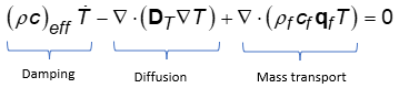 | (4–92) |
where:
 = thermal conductivity (Units: Mass * Length *
Temperature-1 *
Time-3) = thermal conductivity (Units: Mass * Length *
Temperature-1 *
Time-3) |
 = fluid density calculated as = fluid density calculated as  . . |
The form of  depends on the TB table definition:


The stability of the Galerkin formulation is measured in terms of the non-dimensional criteria called the element Peclet number, which calculates the ratio between the mass transport term and the diffusion term. The Peclet number is calculated in a similar manner to Equation 4–1 in the Thermal Analysis Guide, where the velocity vector is replaced by the fluid flow flux.
To ensure Galerkin formulation stability, the recommended Peclet number should be < 1.
The material properties for porous media analysis include solid skeleton and pore-fluid properties. Define material model constants for a porous medium (TB,PM).
The following material-property options
(TBOPT) are available for defining porous media:
Fluid permeability (PERM)
Biot (BIOT)
Solid (SP)
Fluid (FP)
Degree of saturation (DSAT)
Relative permeability (RPER)
Gravity magnitude (GRAV)
Define constants (Cn) via
TBDATA (or TBPT, as applicable).
4.12.3.1. Permeability (TB,PM,,,,TBOPT =
PERM)
The permeability properties can be isotropic, orthotropic or anisotropic. The full 3 x 3 permeability matrix is:

Define up to nine constants:
Isotropic permeability matrix -- Define  only. (The only. (The  and and  values are assumed to be values are assumed to be  . ) . ) |
Orthotropic permeability matrix -- Enter
three constants:  , , and and  . The program assigns values of zero to the off-diagonal
permeability constants ( . The program assigns values of zero to the off-diagonal
permeability constants ( ). ). |
Anisotropic permeability matrix -- If you
define the first six constants ( ), the program makes the permeability matrix symmetric (that
is, ), the program makes the permeability matrix symmetric (that
is,  ). ). |
| General nonsymmetric anisotropic permeability matrix -- Define all nine constants. |
| Constant | Meaning | Units |
|---|---|---|
| C1 |

| Length/Time |
| C2 |

| |
| C3 |

| |
| C4 |

| |
| C5 |

| |
| C6 |

| |
| C7 |

| |
| C8 |

| |
| C9 |

|
All defined constants are based on the element coordinate system. By default, the element coordinate system is the global coordinate system.
4.12.3.2. Biot Coefficient (TB,PM,,,,
TBOPT = BIOT)
Define the Biot coefficient and Biot modulus.
If the Biot coefficient remains undefined, the program assigns a default value of 1. If the Biot modulus remains undefined, the porous media is assumed to be incompressible.
| Constant | Meaning | Property | Units |
|---|---|---|---|
| C1 |

| Biot coefficient | Dimensionless |
| C2 |

| Biot modulus | Force/Length2 |
If solid property and/or fluid property is defined (TB,PM,,,,SP/FP), the Biot coefficient and Biot modulus are overwritten with values calculated as described in Porous Media Mechanics.
4.12.3.3. Solid Property (TB,PM,,,,
TBOPT = SP)
Defining either of the available constants is optional:
If the bulk modulus of the solid skeleton is not defined, the solid skeleton is assumed to be incompressible.
If the specific weight of the solid skeleton is defined, the program considers it to be a body force.
| Constant | Meaning | Property | Units |
|---|---|---|---|
| C1 |

| Bulk modulus of solid skeleton | Force/Length2 |
| C2 |

| Specific weight of solid skeleton | Force/Length3 |
4.12.3.4. Fluid Property (TB,PM,,,,
TBOPT = FP)
Defining any of the three available constants is optional:
If the bulk modulus of the fluid is not defined, the fluid is assumed to be incompressible.
If the specific weight of the fluid is defined, the program considers it to be a body-force load.
| Constant | Meaning | Property | Units |
|---|---|---|---|
| C1 |

| Bulk modulus of fluid | Force/Length2 |
| C2 |

| Specific weight of fluid | Force/Length3 |
| C3 |

| Porosity | Dimensionless |
4.12.3.5. Degree of Saturation (TB,PM,,,,
TBOPT
= DSAT)
Define the degree of saturation as a function of pore pressure (TBPT). Pore-pressure values can be negative only (partially saturated flow), and the degree of saturation lies between 0 and 1. If undefined, the degree of saturation defaults to 1.
| Constant | Meaning | Property | Units |
|---|---|---|---|
| C1 |

| Pressure | Force/Length2 |
| C2 |

| Degree of fluid saturation | None |
4.12.3.6. Relative Permeability (TB,PM,,,,
TBOPT
= RPER)
Define the relative permeability as a function of pore pressure (TBPT). Pore-pressure values can be negative only (partially saturated flow), and relative permeability lies between 0 and 1. If undefined, the relative permeability defaults to 1.
| Constant | Meaning | Property | Units |
|---|---|---|---|
| C1 |

| Pressure | Force/Length2 |
| C2 |

| Relative permeability | None |
4.12.3.7. Gravity Magnitude (TB,PM,,,,
TBOPT
= GRAV)
Define the magnitude of gravity.
| Constant | Meaning | Property | Units |
|---|---|---|---|
| C1 |

| Gravity magnitude | Force/Length2 |
If solid and/or fluid properties are defined (TB,PM,,,,SP/FP) and gravity magnitude is defined (TB,PM,,,,GRAV), bulk density is calculated as described in Porous Media Mechanics.
If gravity magnitude is not defined, it is assumed to be 1.
The units of permeability are always defined as Length/Time, according to Darcy's law. If the specific weight of
the fluid  is not defined (
TBOPT = FP), it is
assumed to be 1 (unit = Force/Length3).
Thermal conductivity (TBOPT = COND), solid-skeleton
specific heat (TBOPT = SPHT), and fluid specific heat
(TBOPT = FLSPHT) are defined via
TB,THERM. For more information about defining thermal material
properties, see Thermal Properties.
The solid-skeleton volumetric thermal-expansion coefficient  is the sum of the linear thermal-expansion coefficients defined via
TB,CTE (or MPTEMP and
MPDATA,CTEX/Y/Z).
is the sum of the linear thermal-expansion coefficients defined via
TB,CTE (or MPTEMP and
MPDATA,CTEX/Y/Z).
The fluid volumetric thermal expansion coefficient is directly defined via TB,CTE,,,,FLUID.
A soil-consolidation problem is typically a transient analysis
(ANTYPE,SOIL or ANTYPE,TRANS). A transient
analysis considers all rate ( ,
,  ,
,  ) and acceleration (
 ) terms in the governing equations (Equation 4–87, Equation 4–88, and Equation 4–92).
In a geostatic analysis (ANTYPE,SOIL with SSOPT,GEOSTATIC), all transient terms (acceleration and rate) are ignored.
In a static analysis (ANTYPE,STAT), all
acceleration terms are ignored; however, the program accounts for the following rate
terms: volumetric strain rate ( ), pressure rate (
 ), free-strain rate
  , and specific heat damping
  in the mass-balance and heat-transfer equations.
In a static analysis, applying fluid flow (FLOW) and heat flow (HEAT) (via the nodal-force command F) is not supported. If those are needed, use a transient analysis.
Soil embankments and dams are examples of semi-saturated porous media. Such structures are often characterized by a phreatic line (free water surface). The soil below the phreatic line is fully saturated, while the soil above is partially saturated. Partially saturated flow results in negative pore pressures. The presence of negative pore pressures is beneficial to the soil. It assures some cohesion in the soil, essential for maintaining its structural integrity.
Partially saturated porous media flow does not introduce any new degrees of freedom to
coupled pore-pressure-thermal elements
(CPTnnn); that is, pore pressure is still the extra
degree of freedom in addition to the displacement degrees of freedom). Partially
saturated behavior is modeled by introducing two new parameters, the degree of
saturation and the relative permeability, both of which are functions of the negative
pore pressure. The relationships can be defined in tabular form
(TB,PM,,,,DSAT and TB,PM,,,,RPER,
respectively).
CPT damping refers to Rayleigh damping, available for
CPTnnn elements via the
TB,SDAMP,,,,ALPD/BETD command.
For more information, see Example: Initial Degree of Saturation and Relative Permeability in the Advanced Analysis Guide.