For current-technology elements, PLANE292 and SOLID278, you can choose between the Galerkin or the Streamline Upwind Petrov-Galerkin (SUPG) Formulation described in this section. Instead, only the Galerkin formulation is available for legacy elements, PLANE55 and SOLID70.
The stability of the Galerkin formulation is measured in terms of the non-dimensional criteria called the element Peclet number (Gresho 59):
(4–1) |
where:
|
|
|
|
|
|
|
|
| (For
PLANE292 and SOLID278,
you can use either the MP or the TB
command to specify |
|
|
The magnitude of the velocity vector is calculated as follows:
(4–2) |
where:
= fluid velocity (mass transport) in x direction
= fluid velocity (mass transport) in y direction
= fluid velocity (mass transport) in z direction (relevant only
for solid elements)
To specify velocity components in your model, issue the BF command for SOLID278 and PLANE292 or the R command for PLANE55 or SOLID70 (see details in Table 4.1: Specifications for Including Mass Transport in an Analysis).
Elements PLANE55 or SOLID70 are restricted to Pe<1, and if this condition is not met, an error message is printed during element formulation. When this error occurs, you must reduce the element size in the direction of the velocity vector to reduce Pe to less than one and enable the solution or switch to one of the current technology elements, SOLID278 or PLANE292 as described in the next section.
There is no restriction on Pe for the current-technology elements, PLANE292 and SOLID278. The Streamline Upwind Petrov-Galerkin (SUPG) formulation is available for these elements, and it smooths oscillations without increasing solution time compared to the Galerkin formulation. You can also add one of three additional discontinuity capturing (DC) terms to the governing equation when using the SUPG formulation to further smooth persistent oscillations if they arise in high Pe conditions:
| DC1 applies isotropic consistent diffusion to the flow field and works well for simple unidirectional flow fields, but it is not able to stabilize more complex flows. For example, a rotational flow field will require either the DC2 or DC3 term. |
| DC2 applies isotropic diffusion to the flow field, and works well for more complex flows, for example rotational flow fields. |
| DC3 applies anisotropic diffusion as a consistent additional diffusion orthogonal to the flow field. Like DC2, it is useful for complex flow fields. |
Since all of the DC terms make the problem nonlinear, their use to stabilize the solution requires an iterative solution and increases solution time.
When using the SUPG formulation, you can activate one of the three DC terms to
smooth oscillations if they arise in your solution by setting real constants listed
in the table below using the R and RMORE
commands. To include a DC term to include in your analysis you must set
DC1, DC2, or
DC3 to a non-zero value, typically 1.0. You can also
modify the thermal gradient threshold value (TGRADMAG),
above which the selected DC term will be applied (default is 1.0e-6). If you don't
specify any real constants, the default setting is to base the analysis on the SUPG
formulation without including any DC terms.
| Real Constants Used to Activate the SUPG formulation and one of the three DC terms[a] | |||
| No. [b] | Name | Default | Description |
| 2 |
SUPG
| 1.0 | Acts as a multiplier on the stabilizing term of the
SUPG formulation and enables you to choose also a DC term to smooth
oscillations. To activate the Galerkin Formulation, use a small number(1.e-12), as an exact zero value reverts back to 1.0 internally and enables SUPG formulation. |
| 3 |
TGRADMAG
| 1.0e-6 | Thermal gradient threshold value, above which the DC
term that you select will be applied. If the thermal gradient is
less than the value you specify for
TGRADMAG, the DC term is not applied,
and vice versa, if it is greater, the nonlinear stabilizing DC term
will be applied. |
| 5 |
DC1
[c]
| 0.0 | Any non-zero value (typically 1.0) selects the DC1 term to be added to your analysis and acts as a multiplier on this stabilizing term. |
| 6 |
DC2
[c]
| 0.0 | Any non-zero value (typically 1.0) selects the DC2 term to be added to your analysis and acts as a multiplier on this stabilizing term. |
| 7 |
DC3
[c]
| 0.0 | Any non-zero value (typically 1.0) selects the DC3 term to be added to your analysis and acts as a multiplier on this stabilizing term. |
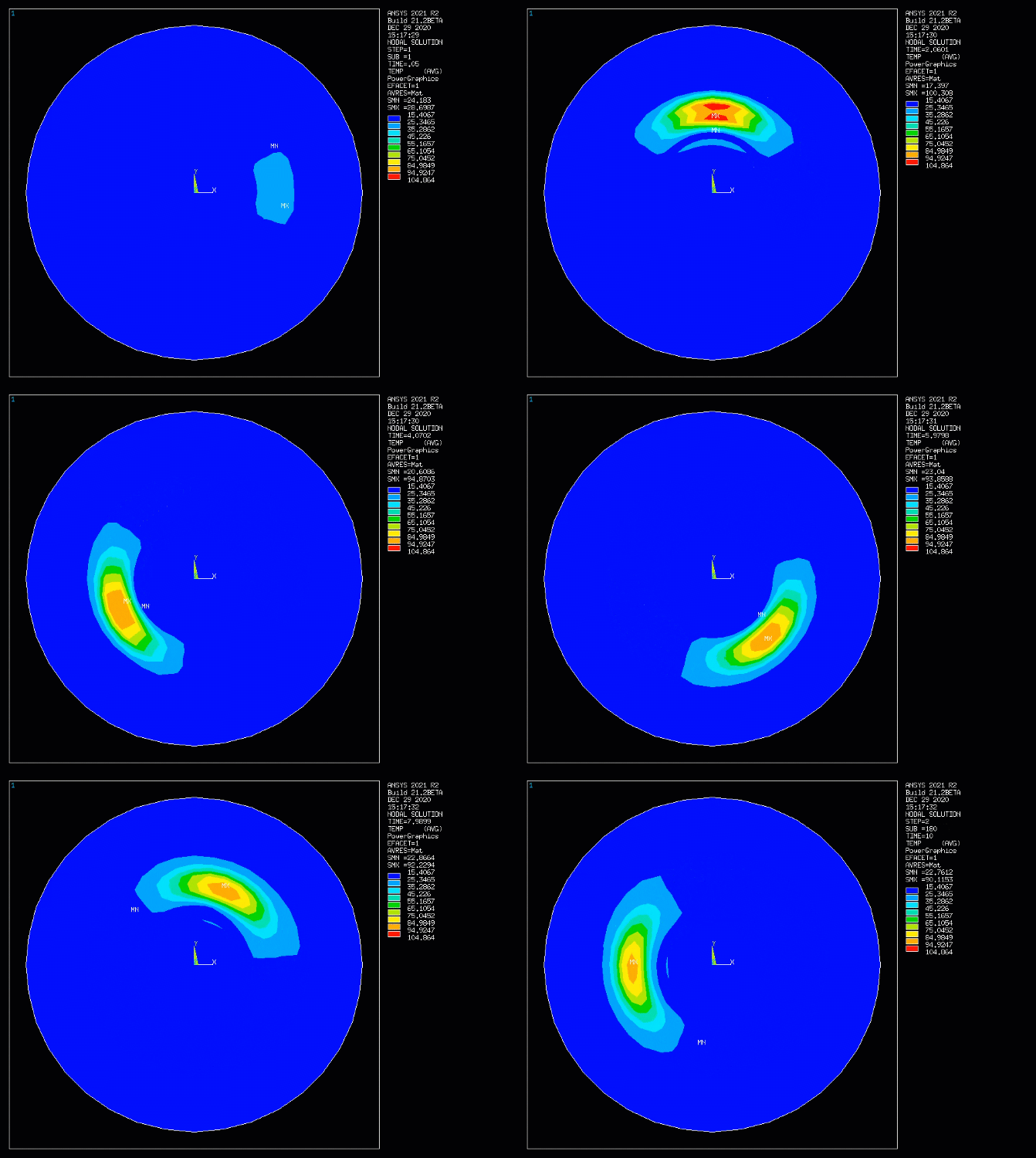
The SUPG formulation and DC terms enable a smooth solution for the simulation of heat transfer by mass transport in complex flows with discontinuities. This capability is seen in the example below.
Example 4.1: Simulating Heat Transfer in the Rotating Flow of a Brake Disk
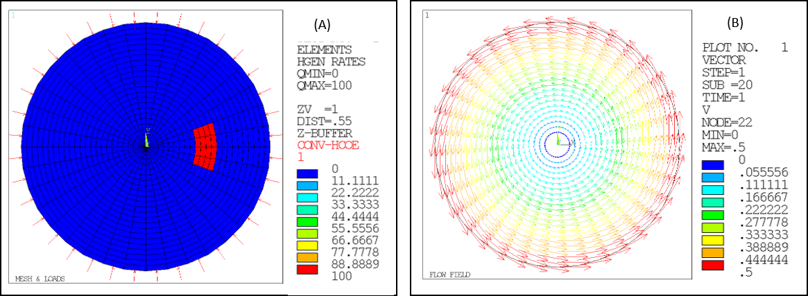
The setup of an analysis simulating the dissipation of heat by the rotating flow of a spinning brake disk is illustrated in Figure 4.1: Simulated Mass Transport of Heat - Brake Disk with Rotating Flow (A:Mesh and Loads, B:Prescribed flow field). A transient heat source is generated by friction when the brake pad is in contact with the brake disk. This is modeled as a heat generation thermal load in the first loadstep. In the second loadstep, the heat generation is removed. The region for heat generation is indicated in the figure by the red patch in A. Since the analysis is a 2D model, the heat loss to the ambient environment is modeled as a convection boundary condition at the circumference of the disk as indicated by the red arrows in A. The rotational flow field created by the spinning disk, shown in B, is the prescribed velocity field input for the simulation of advection heat transfer.
Figure 4.1: Simulated Mass Transport of Heat - Brake Disk with Rotating Flow (A:Mesh and Loads, B:Prescribed flow field)

The animation below shows the transient computed temperature field in the rotating disk.


