The following examples are available:
This example problem shows how to perform a steady-state conduction current analysis.
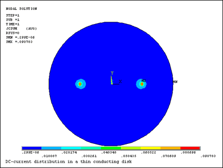
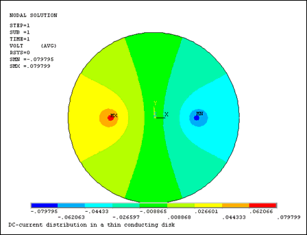
A current I is applied to a thin disk of radius r = a. As shown in the following figure, the current enters and leaves via point electrodes located at r = b, ϕ = 0 and r = b, ϕ = π. Find the potential and dc-current distributions in the disk.
The geometric and electrical parameters are:
| Radius a = 20 cm |
| Distance from the center to the point electrodes b = 10 cm |
| Applied Current I = 1 mA |
| Disk Resistivity ρ = 100 Ωm |
To obtain an accurate field distribution, the disc area is densely meshed with triangle-shaped PLANE230 electric elements. A VOLT degree of freedom constraint is applied to the center of the disk. Current loads are applied as concentrated nodal loads. A cylindrical coordinate system is used.
Table 12.19: Electric Potential at Points with Coordinates r = a and ϕ
| ϕ (degrees) | Electric Potential (V) | |
|---|---|---|
| Computed | Target [1 ] | |
| 0 | –.03501 | –.03497 |
| 10 | –.03399 | –.03392 |
| 20 | –.03124 | –.03110 |
| 30 | –.02708 | –.02716 |
| 40 | –.02269 | –.02271 |
| 50 | –.01814 | –.01810 |
| 60 | –.01360 | –.01349 |
| 70 | –.00880 | –.00894 |
| 80 | –.00438 | –.00445 |
| 90 | 0.0 | 0.0 |
The following figures display the potential and dc-current distributions in the disk.
You can perform this example steady-state analysis using the Mechanical APDL commands shown below. Text prefaced by an exclamation point (!) is a comment.
/batch,list
/title, DC-current distribution in a thin conducting disk
a=20.e-2               ! disk radius, m
b=10.e-2               ! electrode distance from the center, m
I=1.e-3                ! current, A
rho=100                ! resistivity, Ohm*m
/nopr

/PREP7
! Model and meshing
et,1,PLANE230          ! electric element type
mp,rsvx,1,rho          ! resistivity

cyl4,0,0,0,0,a,360     ! circular area
esize,,64
msha,1,2D             ! mesh with triangles
amesh,1

! Boundary conditions
csys,1                 ! cylindrical coordinate system
d,node(0,0,0),volt,0   ! ground center node

! Nodal current loads
f,node(b,0,0),amps,-I
f,node(b,180,0),amps,I

fini

/solu
antype,static          ! steady-state current conduction
solve
fini

/post1
plnsol,volt            ! plot electric potential
plnsol,jc,sum          ! plot current density vector magnitude

*dim,value,,10,2
*dim,coord,,10,2

*do,i,1,10
! coordinates of solution point
r=a $   phi=(i-1)*10
coord(i,1)=r
coord(i,2)=phi
! Mechanical APDL solution
value(i,1)=volt(node(a,(i-1)*10,0))
*enddo
! Analytical solution
*vfill,value(1,2),data,-0.034969,-0.033923,-0.031098,-0.027163,-0.022709
*vfill,value(6,2),data,-0.018095,-0.013485,-0.008937,-0.004451,0.

/com,----------------  VOLT SOLUTION  ----------------
/com,
/com,    R    |   PHI   |  Mechanical APDL |    TARGET
/com,
*vwrite,coord(1,1),coord(1,2),value(1,1),value(1,2),
(1X,' ',F6.1,'    ',F6.1,'   ',F11.6,'    ',F11.6)
/com,-------------------------------------------------

fini
This problem evaluates conductance between parallel plate electrodes. The objective is to calculate the self and mutual conductance coefficients between two parallel plate electrodes.
The model consists of two parallel plate electrodes, 3 m in length, with a gap of 2 m and a conductivity of 10. One electrode represents the ground, and 100 volts is applied to the other electrode. The target conductance is 15.
/title,Conductance between parallel plate electrodes using GMATRIX

/com Input data
/com sigma : conductivity
/com g     : gap between electrodes
/com w     : electrode width
/com l     : length
/com
/com Target
/com
/com G = sigma w l / g : conductance between parallel plate electrodes
!
g=2                    ! gap between electrodes
w=3                    ! electrode width
l=1                    ! length
sigma=10	               ! conductivity
!
gt=sigma*w*l/g         ! target conductance
!
/prep7
et,1,230
mp,rsvx,1,1/sigma
!
n,1,0,0
n,2,w,0
n,3,w,g
n,4,0,g
e,1,2,3,4
!
nsel,s,loc,y,g           ! electrode
cm,comp1,node
d,all,volt,100
!
nsel,s,loc,y,0           ! ground
cm,comp2,node
d,all,volt,0
!
nsel,all
!
gmatrix,1,'comp',2,0      ! compute conductance matrix
gc=gmatrix(1,1,1)         ! computed conductance
finish
A time-harmonic voltage of amplitude Vo is applied to a barium titanate parallel plate capacitor with circular plates of radius a and dielectric thickness d. The dielectric has relative permittivity εr and loss tangent tanδ. Perform a harmonic analysis to determine the capacitor admittance (Y) in the frequency (f) range of 0 to 1 MHz, and find the dissipated power at 1 MHz.
The geometric and electrical parameters are:
| Radius a = 9 cm |
| Thickness d = 0.1 cm |
| Relative Permittivity εr = 1143 |
| Loss tangent tanδ = 0.0105 |
| Voltage amplitude Vo = 50 volts |
| Frequency f = 0 to 1 MHz |
The capacitor is modeled using the axisymmetric option of PLANE230 electric elements. Electrodes are defined by coupling VOLT degrees of freedom on the major surfaces of the capacitor. The bottom electrode is grounded, and a voltage load Vo is applied to the top electrode.
Electric admittance (Y) is calculated at ten frequencies between 0 and 1 MHz using the reaction current on the loaded electrode. Results are compared with target values obtained from the following analytical expression:
Y = 2πfC(tanδ+j)
where:
and j = imaginary unit.
Power dissipation at f = 1 MHz is calculated in /POST1 by summing up the Joule heat rates over the elements. The result is compared with the following analytical expression for the time-average power dissipated in the capacitor:
As shown in the following table, the Mechanical APDL electric admittance (Y) results agree with those from the analytical expression given above.
Table 12.20: Electric Admittance (Y)
| Frequency (MHz) | Admittance Amplitude (S) [1] |
|---|---|
| 0.0 | 0.1618 |
| 0.2 | 0.3236 |
| 0.3 | 0.4855 |
| 0.4 | 0.6473 |
| 0.5 | 0.8091 |
| 0.6 | 0.9709 |
| 0.7 | 1.1327 |
| 0.8 | 1.2945 |
| 0.9 | 1.4564 |
| 1.0 | 1.6182 |
The power dissipated at a frequency of 1 MHz is 21.2 watts.
You can perform this example harmonic analysis using the Mechanical APDL commands shown below. Text prefaced by an exclamation point (!) is a comment.
Besides commands to perform this analysis using the PLANE230 electric elements, this command listing includes the commands to do the same analysis using PLANE121 electrostatic elements.
/batch,list
/title, Harmonic response of a lossy capacitor
/com,
/com,  Problem parameters:
a=9.e-2                        ! radius, m
d=0.1e-2                       ! thickness, m
epsr=1143                      ! relative permittivity
tand=0.0105                    ! loss tangent
Vo=50                          ! voltage amplitude, V
f1=0                           ! begin frequency, Hz
f2=1.e6                        ! end frequency, Hz
eps0=8.854e-12                 ! free space permittivity, F/m
Pi=acos(-1)
C=epsr*eps0*Pi*a**2/d          ! capacitance, F
P2d=Pi*f2*Vo**2*C*tand         ! power dissipation at freq. f2, watt

/nopr
/PREP7
et,1,PLANE230,,,1              ! axisymmetric electric element
emunit,epzro,eps0              ! specify free-space permittivity
mp,perx,1,epsr                 ! electric material properties
mp,lsst,1,tand

rect,,a,,d                     ! model and mesh
esize,d/2
amesh,1

! Boundary conditions and loads
nsel,s,loc,y,0
cp,1,volt,all                  ! define bottom electrode
*get,n_grd,node,0,num,min      ! get master node on bottom electrode
nsel,s,loc,y,d
cp,2,volt,all                  ! top electrode
*get,n_load,node,0,num,min     ! get master node on top electrode
nsel,all
d,n_grd,volt,0                 ! ground bottom electrode
d,n_load,volt,Vo               ! apply voltage load to top electrode
fini

/solu
antype,harm                    ! harmonic analysis
harfrq,f1,f2                   ! frequency range
nsubs,10                       ! number of substeps
outres,all,all                 ! write all solution items to the result file
kbc,1                          ! stepped load
solve
fini

/post1
/com,Calculate power dissipation at frequency = %f2%, Hz
set,last                       ! read last data set
etab,jh,jheat                  ! fill etable with Joule heat rates per unit volume
etab,vol,volu                  ! fill etable with element volumes
smult,dpower,jh,vol            ! fill etable with element Joule heat rates
ssum                           ! sum element Joule heat rates
/com,Expected power dissipation = %P2d%, watt
fini

/post26
rfor,2,n_load,amps             ! reaction current I
prod,3,2,,,Y_ANSYS,,,1/Vo      ! Y_ansys = I/V
prod,4,1,,,,,,2*Pi*C           ! 2*Pi*f*C
cfact,tand,,,1
add,5,4,4,,Y_TARGET            ! Y_target = 2*Pi*f*C*(tand+j)
prcplx,1
prvar,Y_ANSYS,Y_TARGET
fini

/com,
/com, *** Perform same frequency sweep using electrostatic elements
/com,
/PREP7
et,1,PLANE121,,,1              ! axisymmetric electrostatic element
fini

/solu
antype,harm                    ! harmonic analysis
harfrq,f1,f2                   ! frequency range
nsubs,10                       ! number of substeps
outres,all,all                 ! write all solution items to the result file
kbc,1                          ! stepped load
solve
fini

/post1
/com,Calculate power dissipation at frequency = %f2%, Hz
set,last                       ! read last dataset
etab,jh,jheat                  ! fill etable with Joule heat rates per unit volume
etab,vol,volu                  ! fill etable with element volumes
smult,dpower,jh,vol            ! fill etable with element Joule heat rates
ssum                           ! summ up element Joule heat rates
/com,Expected power dissipation = %P2d%, watt
fini

/post26
rfor,2,n_load,chrg             ! reaction charge Q
cfact,0,2*Pi
prod,3,1,2,,Y_ANSYS,,,,1/Vo    ! Y_ansys = j*2*Pi*Q/Vo
prod,4,1,,,,,,2*Pi*C           ! 2*Pi*f*C
cfact,tand,,,1
add,5,4,4,,Y_TARGET            ! Y_target = 2*Pi*f*C*(tand+j)
prcplx,1
prvar,Y_ANSYS,Y_TARGET
fini
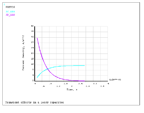
A parallel plate capacitor filled with a lossy dielectric, characterized by relative permittivity εr and resistivity ρ, is connected, in series with a resistor R, to a source of constant voltage U. The switch closes at time t = 0. Find the electric field and current density distributions in the capacitor as functions of time.
The capacitor and circuit parameters are:
| Length a = 3 cm |
| Width b = 1 cm |
| Thickness d = 0.5 cm |
| Permittivity (relative) = 12 |
| Resistivity = 150 Ωm |
| Resistance R = 1 kΩ |
| Voltage U = 12 volts |
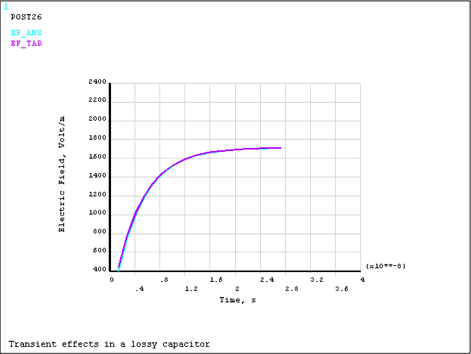
The lossy capacitor is modeled with SOLID231 electric elements. Electrodes are defined by coupling VOLT degrees of freedom on the major surfaces of the capacitor. Lumped circuit components are modeled using CIRCU124 elements and they are connected to the capacitor via the master nodes. A transient analysis is performed to determine the electric field variation in the capacitor with time. Computed results for a selected element are compared in /POST26 to the values derived from the following analytical expression for the electric field:
E(t) = Es{1 - exp (-t/τ)}
where:
Es = steady-state electric field, Volts/m
S = capacitor plate area, m2
τ = time constant, seconds
and they are defined by:
S = ab
The following figures display the electric field and current density distributions as functions of time.
You can perform this example transient analysis using the Mechanical APDL commands shown below. Text prefaced by an exclamation point (!) is a comment.
Besides /POST26 commands to display the electric field and current density, this command listing includes the commands to print electric field, current density, electric flux density, and Joule heat rate. The current density and Joule heat rate output quantities are included to illustrate the coupling to magnetic and thermal analyses using companion magnetic and thermal elements, respectively.
/batch,list
/title, Transient effects in a lossy capacitor
/com,
/com,  Problem parameters:
a=3.e-2           ! length, m
b=1.e-2           ! width, m
S=a*b             ! area, m**2
d=0.5e-2          ! thickness, m
epsr=12           ! relative permittivity of dielectric
eps0=8.854e-12    ! free space permittivity, F/m
rho=150           ! resistivity of dielectric, Ohm*m,
R=1000            ! resistance, Ohm
U=12              ! voltage, V
Es=U/(S*R/rho+d)  ! steady-state electric field, V/m
tau=epsr*eps0*S*R/(S*R/rho+d) ! time constant, s

/nopr
/PREP7
emunit,epzro,eps0 ! Specify free-space permittivity

! Element attributes
et,1,CIRCU124     ! Resistor
et,2,CIRCU124,4   ! Voltage source
et,3,SOLID231     ! 20-node brick electric solid
r,1,R             ! Real constants for circuit elements
r,2,U
mp,rsvx,1,rho     ! Electric properties
mp,perx,1,epsr

! Modeling and meshing
type,3
mat,1
block,,d,,a,,b
esize,d/2
vmesh,1

nsel,s,loc,x,0
cp,1,volt,all           ! Couple nodes to model right electrode
*get,n1,node,0,num,min  ! Get master node on right electrode
nsel,s,loc,x,d
cp,2,volt,all           ! Couple nodes to model left electrode
*get,n2,node,0,num,min  ! Get master node on left electrode
nsel,all

! Circuit mesh
*get,nmax,node,0,num,max
n3=nmax+1
n4=n3+1
n,n3,a/2,-a
n,n4,a/2,-a
type,1                  ! resistor
real,1
e,n1,n3
type,2                  ! voltage source
real,2
e,n3,n2,n4
d,n2,volt,0             ! ground node
fini

/solu
antype,transient        ! transient analysis
t1=6*tau
time,t1                 ! set analysis time
deltim,t1/100           ! set time step
outres,all,5            ! write results at every 5th substep
ic,all,volt,0           ! initial conditions for VOLT
solve
fini

! Select nodes and elements for postprocessing
n_post=node(d/2,a/2,b/2)
nsel,s,node,,n_post
esln,s
*get,e_post,elem,0,num,min
allsel

/com, *** Results verification
/post26
numvar,20

! Electric field
esol,2,e_post,,EF,x,EF_ANS
exp,3,1,,,,,,-1/tau,-1         ! -exp(-t/tau)
filldata,4,,,,1                ! 1
add,5,4,3,,EF_TAR,,,Es,Es      ! E=Es*(1-exp(-t/tau))

! Conduction current
esol,6,e_post,,JC,x,JC_ANS
prod,7,5,,,JC_TAR,,,1/rho      ! Jc=E/rho

! Electric flux density
esol,8,e_post,,NMISC,1,D_ANS
prod,9,5,,,D_TAR,,,epsr*eps0   ! D=epsr*eps0*E

! Displacement and total (displacement+conduction) currents
esol,10,e_post,,JS,x,JS_ANS
add,11,10,6,,JD_ANS,,,,-1      ! Jd=Js-Jc
deriv,12,9,1,,JD_TAR           ! Jd=dD/dt
add,13,7,12,,JS_TAR

! Joule heat generation rate per unit volume
esol,14,e_post,,JHEAT,,HGEN_ANS
prod,15,5,7,,HGEN_TAR! Jheat=E*Jc

prvar,EF_ANS,EF_TAR,D_ANS,D_TAR
prvar,JC_ANS,JC_TAR,JD_ANS,JD_TAR,JS_ANS,JS_TAR
prvar,HGEN_ANS,HGEN_TAR

/axlab,x, Time, s
/axlab,y, Electric Field, Volt/m
plvar,EF_ANS,EF_TAR            ! Plot computed and expected EF
/axlab,y, Current density, A/m**2
plvar,JC_ANS,JD_ANS,JS_ANS     ! Plot computed currents
fini

/com, *** Coupling to thermal analysis
/PREP7
et,1,0
et,2,0
et,3,90               ! companion thermal element
esel,s,elem,,e_post
ldread,hgen,,5,,,,rth ! read heat generation from the 5th substep
bfelist,all,hgen
ldread,hgen,,,,,,rth  ! read heat generation from the last substep
bfelist,all,hgen
esel,all
fini

/com, *** Coupling to magnetic analysis
/PREP7
et,3,236           ! companion magnetic element
esel,s,elem,,e_post
ldread,js,,5,,,,rth   ! read current from the 5th substep
bfelist,all,js
ldread,js,,,,,,rth    ! read current from the last substep
bfelist,all,js
esel,all
fini
Another Ansys, Inc., publication, the Mechanical APDL Verification Manual, contains several examples of current conduction analysis:


