A rectangular beam with perforated holes is modeled to compute the effective damping coefficient, stiffness coefficient, and damping ratio. The surface of the structure is modeled with FLUID136 elements to represent the thin film. The structure is modeled with SOLID185 elements. This example computes the Rayleigh damping coefficients (α and β) and modal damping ratios ξi for use in a transient dynamic analysis.
The problem is defined as an extension to the earlier squeeze film example. After modeling the fluid domain, the structure of the beam is modeled and meshed with SOLID185 elements. A modal analysis is performed on the structure and the first two eigenvalues and eigenvectors are computed. RMFLVEC is used to extract the eigenvectors for use in the modal projection method to compute the thin-film damping parameters. The command macro ABEXTRACT is used to compute the Rayleigh parameters from the lowest two eigenmodes. Modal damping ratios are also provided by the ABEXTRACT macro for the two eigenmodes.
Table 4.1: Modal Damping Parameters for First Two Eigenfrequencies lists the results from the damping parameter extraction. Computed Rayleigh parameters are: ALPHAD=65212, BETAD=1.829e-8. The input file for this example is shown below.
Table 4.1: Modal Damping Parameters for First Two Eigenfrequencies
| Frequency (Hz.) | Modal Damping Coefficient | Modal Squeeze Stiffness Coefficient | Damping Ratio | Stiffness Ratio |
|---|---|---|---|---|
| 55294 | 67419 | .2758e9 | .9703e-1 | .2285e-2 |
| 157497 | 83123 | .3568e10 | .4200e-1 | .3644e-2 |
The input file for this example is shown below.
/batch,list
/PREP7
/title, Damping Ratio and Rayleigh Damping Calculations for a Perforated Plate
/com    uMKS units

ET, 1,136,1    ! 4-node option, High Knudsen Number
ET, 2,138,1	    ! Circular hole option, Hugh Knudsen Number
ET,3,185,,3    ! Structural element

s_l=100                         ! Half Plate length (um)
s_l1=60                         ! Plate hole location
s_w=20                          ! Plate width
s_t=1                           ! Plate thickness
c_r=3                           ! Hole radius
d_el=2                          ! Gap
pamb=.1  	                     ! ambient pressure (MPa)
visc=18.3e-12                   ! viscosity kg/(um)(s)
pref=.1                         ! Reference pressure (MPa)
mfp=64e-3			                  ! mean free path (um)
Knud=mfp/d_el                   ! Knudsen number

mp,visc,1,visc  		! Dynamic viscosity gap
mp,visc,2,visc			! Dynamic viscosity holes
mp,ex,3,79e3	                ! Gold
mp,dens,3,19300e-18
mp,nuxy,3,.1


r,1,d_el,,,pamb			! Real constants - gap
rmore,pref,mfp

r,2,c_r,,,pamb			  ! Real constants - hole
rmore,pref,mfp

! Build the model

rectng,-s_l,s_l,-s_w,s_w            ! Plate domain
pcirc,c_r                           ! Hole domain
agen,3,2,,,-s_l1/3
agen,3,2,,,s_l1/3
ASBA, 1, all

TYPE, 1
MAT, 1
smrtsize,4
AMESH, all                          ! Mesh plate domain


! Begin Hole generation
*do,i,1,5
 nsel,all
 *GET, numb, node, , num, max       ! Create nodes for link elements
 N, numb+1,-s_l1+i*s_l1/3,,
 N, numb+2,-s_l1+i*s_l1/3,, s_t
 TYPE,2
 MAT, 2
 REAL,2
 NSEL, all
 E, numb+1, numb+2         ! Define 2D link element
 ESEL, s, type,,1
 NSLE,s,1
 local,11,1,-s_l1+i*s_l1/3
 csys,11
 NSEL,r, loc, x, c_r       ! Select all nodes on the hole circumference
 NSEL,a, node, ,numb+1
 *GET, next, node, , num, min
 CP, i, pres, numb+1, next
 nsel,u,node, ,numb+1
 nsel,u,node, ,next
 CP, i, pres,all 	!Coupled DOF set for constant pressure
 csys,0
*enddo
 ! End hole generation

esize,,2
type,3
mat,3
real,3
vext,all,,,,,s_t              ! Extrude structural domain


nsel,s,loc,x,-s_l
nsel,a,loc,x,s_l
nsel,a,loc,y,-s_w
nsel,a,loc,y,s_w
nsel,r,loc,z,-1e-9,1e-9
d,all,pres              ! Fix pressure at outer plate boundary
nsel,all

esel,s,type,,2
nsle,s,1
nsel,r,loc,z,s_t
d,all,pres,0           ! P=0 at top of plate
dlist,all

esel,s,type,,1
nsle,s,1
nsel,u,cp,,1,5
cm,FLUN,node
allsel

nsel,s,loc,x,-s_l
nsel,a,loc,x,s_l
d,all,ux
d,all,uy
d,all,uz

allsel

fini

/solu
antype,modal			! Modal analysis
modopt,lanb,2			! Extract lowest two eigenmodes
eqslv,sparse
mxpand,2			     ! Expand lowest two eigenmodes
solve
fini

/post1
RMFLVEC            ! Extract eigenvectors
fini

/solu
abextract,1,2      ! Extract damping ratios and Rayleigh constants
finish
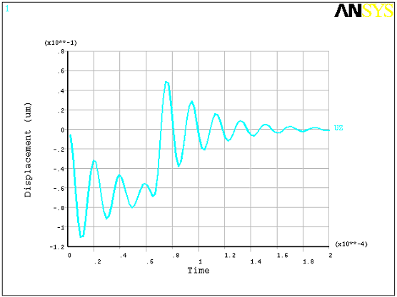
A transient dynamic analysis on the switch can be performed using the extracted damping parameters. The following input illustrates a coupled electrostatic-structural time-transient solution. The electrostatic field is assumed to be normal to the plate in the gap, and fringing effects are ignored. TRANS126 elements are used to model the coupled electrostatic-structural interaction with the switch. The EMTGEN command is used to generate the transducer elements. A step voltage pulse is applied over a short duration (65 micro-seconds) then released. Rayleigh damping parameters, when used, are applied to the global mass (ALPHAD parameter) and stiffness (BETAD parameter) matrices. We want to apply these only to the mass and stiffness matrix of the SOLID185 elements, and not the TRANS126 elements, because doing so may overdamp the system. The TRANS126 elements produce a damping matrix and a stiffness matrix only. Hence, we can use the ALPHAD parameter for the global mass matrix since there is no contribution from the TRANS126 elements. To isolate the SOLID185 elements for beta damping, we can apply the beta damping via a material damping option (MP,BETD). Figure 4.4: Time-Transient Response from Voltage Pulse illustrates the displacement of a node near the center of the plate over time. The maximum amplitude of displacement (0.11 microns) is small enough to ignore large deflection damping effects.
/batch,list
/PREP7
/title, Damped Transient Dynamic Response of an RF MEMS switch
/com    uMKS units
/com,   Small deflection assumption

et,1,200,6
ET,3,185,,3                     ! Structural element

s_l=100                         ! Plate length (um)
s_l1=60                         ! Plate hole location
s_w=20                          ! Plate width
s_t=1                           ! Plate thickness
c_r=3                           ! Hole radius
d_el=2                          ! Gap
pamb=.1  	                       ! ambient pressure (MPa)
visc=18.3e-12                   ! viscosity kg/(um)(s)
pref=.1                         ! Reference pressure (MPa)
mfp=64e-3			                   ! mean free path (um)
Knud=mfp/d_el                   ! Knudsen number

mp,ex,3,79e3	                   ! Gold
mp,dens,3,19300e-18
mp,nuxy,3,.1
mp,betd,1,1.829e-8              ! Material damping (from squeeze film results)
! Build the model

rectng,-s_l,s_l,-s_w,s_w         ! Plate domain
pcirc,c_r                        ! Hole domain
agen,3,2,,,-s_l1/3
agen,3,2,,,s_l1/3
ASBA, 1, all

TYPE, 1
MAT, 1
smrtsize,4
AMESH, all                       ! Mesh plate domain

esize,,2
type,3
mat,3
real,3
vext,all,,,,,s_t                 ! Extrude structural domain

nsel,s,loc,x,-s_l
nsel,a,loc,x,s_l
d,all,ux
d,all,uy
d,all,uz

allsel
aclear,all
save

nsel,s,loc,z
cm,base,nodes
emtgen,'base',,,'uz',-d_el      ! generate Transducer elements
allsel,all
nsel,s,loc,z,-d_el
d,all,uz,0
d,all,volt,0
cmsel,s,base
d,all,volt,10
allsel,all
fini
/solu
antyp,trans
alphad,65211   ! alpha damping computed from Squeeze-film theory
kbc,1
time,.000065
deltime,2.0e-6
outres,all,none
outres,nsol,all
solve
time,.0002
cmsel,s,base
d,all,volt,0
allsel,all
solve
fini
n1=node(0,2,0)
/post26
nsol,2,n1,uz
prvar,2
plvar,2
finish


