Problem Description
A rectangular beam with perforated holes under transverse motion is modeled to compute the effective damping and squeeze stiffness coefficients. The thin film surface of the structure is modeled with FLUID136 elements. FLUID138 elements are used to model the hole regions. By altering the boundary condition of the free FLUID138 node, we can simulate different pressure boundary conditions of the hole region. The purpose of the analysis is to compute the equivalent squeeze stiffness and damping coefficient for an assumed uniform plate velocity. A harmonic analysis is performed at 150 kHz. A previous modal analysis indicated that the pertinent eigenfrequency was 150 kHz. Since the analysis is linear, the magnitude of the velocity can be arbitrary for computing the coefficients.
Three cases were considered:
Holes modeled with no resistance (pressure = 0 at hole location, no FLUID138 elements ).
Holes modeled with finite resistance (FLUID138 elements modeled, pressure set to zero on fluid node at top of plate).
Holes modeled with infinite resistance (no pressure specification at hole location, no FLUID138 elements).
Case 1 is typical for large diameter holes compared to the hole depth. Case 3 is typical for very high flow resistance, which happens in the case of narrow and long holes. Case 2 is the most accurate case where the fluid pressure drop is taken into account by the FLUID138 elements.
Results
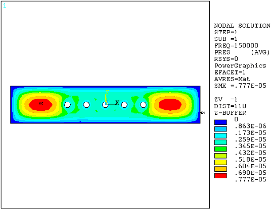
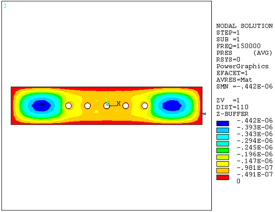
Table 3.2: Beam Model Results Considering Perforated Holes lists the damping and squeeze coefficient results. Figure 3.6: Pressure Distribution (Real Component) and Figure 3.7: Pressure Distribution (Imaginary Component) illustrate the real and imaginary pressure distribution. The input file for case 2 is listed.
Table 3.2: Beam Model Results Considering Perforated Holes
| Frequency (kHz.) | Hole option | Damping Coefficient | Squeeze stiffness coefficient |
|---|---|---|---|
| 150 | Infinite resistance | 2.016e-5 | 1.201 |
| 150 | Finite resistance | 1.325e-5 | .5465 |
| 150 | No resistance | 1.165e-5 | .4607 |
Command Listing
The input file for this example is shown below for the finite-resistance Case 2
/batch,list
/PREP7
/title, Damping and Squeeze film stiffness calculations for a rigid
/com,   plate with holes
/com    uMKS units

ET, 1,136,1                     ! 4-node option, High Knudsen Number
ET, 2,138,1                     ! Circular hole option, High Knudsen Number

s_l=100                         ! Half Plate length (um)
s_l1=60                         ! Plate hole location
s_w=20                          ! Plate width
s_t=1                           ! Plate thickness
c_r=3                           ! Hole radius
d_el=2                          ! Gap
pamb=.1                         ! ambient pressure (MPa)
visc=18.3e-12                   ! viscosity kg/(um)(s)
velo=2000                       ! arbitrary velocity (um/s)
freq=150000                     ! Frequency (Hz.)
pi=3.14159
omega=2*pi*freq                 ! Frequency (rad/sec)
pref=.1                         ! Reference pressure (MPa)
mfp=64e-3                       ! mean free path (um)
Knud=mfp/d_el                   ! Knudsen number

mp,visc,1,visc                  ! Dynamic viscosity gap
mp,visc,2,visc                  ! Dynamic viscosity holes

r,1,d_el,,,pamb                 ! Real constants - gap
rmore,pref,mfp

r,2,c_r,,,pamb                  ! Real constants - hole
rmore,pref,mfp

! Build the model

rectng,-s_l,s_l,-s_w,s_w        ! Plate domain
pcirc,c_r                       ! Hole domain
agen,3,2,,,-s_l1/3
agen,3,2,,,s_l1/3
ASBA, 1, all

TYPE, 1
MAT, 1
smrtsize,4
AMESH, all                      ! Mesh plate domain


! Begin Hole generation
*do,i,1,5
 nsel,all
 *GET, numb, node, , num, max   ! Create nodes for link elements
 N, numb+1,-s_l1+i*s_l1/3,,
 N, numb+2,-s_l1+i*s_l1/3,, s_t
 TYPE,2
 MAT, 2
 REAL,2
 NSEL, all
 E, numb+1, numb+2              ! Define 2D link element
 ESEL, s, type,,1
 NSLE,s,1
 local,11,1,-s_l1+i*s_l1/3
 csys,11
 NSEL,r, loc, x, c_r            ! Select all nodes on the hole circumference
 NSEL,a, node, ,numb+1
 *GET, next, node, , num, min
 CP, i, pres, numb+1, next
 nsel,u,node, ,numb+1
 nsel,u,node, ,next
 CP, i, pres,all                !Coupled DOF set for constant pressure
 csys,0
*enddo
 ! End hole generation

nsel,s,loc,x,-s_l
nsel,a,loc,x,s_l
nsel,a,loc,y,-s_w
nsel,a,loc,y,s_w
nsel,r,loc,z,-1e-9,1e-9
d,all,pres                      ! Fix pressure at outer plate boundary
nsel,all

esel,s,type,,2
nsle,s,1
nsel,r,loc,z,s_t
d,all,pres,0                    ! P=0 at top of plate
dlist,all

allsel

bfe,all,flue,,velo              ! Apply arbitrary velocity
fini

finish
/solu
antyp,harm                      ! Full Harmonic analysis
harfrq,freq
solve
finish
/post1
esel,s,type,,1
set,1,1
etable,presR,pres               ! extract "Real" pressure
etable,earea,volu
smult,forR,presR,earea          ! compute "Real" force
ssum
*get,Fre,ssum,,item,forR
set,1,1,,1
etable,presI,pres               ! extract "Imaginary" pressure
smult,forI,presI,earea          ! compute "Imaginary" pressure
ssum
*get,Fim,ssum,,item,forI

K=abs(Fim*omega/velo)           ! Compute equivalent stiffness
C=abs(Fre/velo)                 ! Compute equivalent damping

/com, ******* Equivalent stiffness  ************************
*stat,K
/com, ******* Equivalent damping  **************************
*stat,C
finish


