Distributed-memory parallel (DMP) processing allows the entire solution phase to run in parallel, including stiffness matrix generation, linear equation solving, and results calculations. This solution mode automatically decomposes the model into smaller domains, transfers the domains to each core, solves each domain simultaneously, and creates a complete solution for the model.
For simulations involving large contact pairs that have a large number of elements relative to the total number of elements in the entire model, the performance of DMP processing can be negatively impacted, particularly in terms of the stiffness matrix generation. These large contact pairs often cause a load imbalance between the cores as every contact pair is restricted to a single core. For example, one core might have two times more computations to perform than another core.
In some cases, using CNCHECK,TRIM can help trim any unnecessary contact/target elements from the larger contact pairs, and therefore improve performance in a distributed-memory parallel (DMP) run.
In most other cases, you can use the command CNCHECK,SPLIT or CNCHECK,DMP to split larger contact pairs into several sub-pairs so that the smaller contact sub-pairs can be distributed into different cores. The contact pair-splitting logic greatly improves load balance between cores, and the time spent on stiffness matrix generation will be much more scalable, particularly at higher core counts. Large bonded and small-sliding contact pairs realize the most benefit from contact pair-splitting.
Because the contact splitting logic internally performs the necessary exchange of data on the boundaries between the split contact pairs, the results with and without contact pair-splitting are essentially identical regardless of whether small or large sliding is involved. Therefore, this method is more advantageous than manual splitting of contact pairs, which generally does not produce the same results before and after splitting.
Contact elements CONTA172, CONTA174, and CONTA177 support contact pair-splitting.
The following contact splitting topics are available:
- 3.16.1. Splitting Large Contact Pairs
- 3.16.2. Defining the Maximum Number of Sub-Pairs
- 3.16.3. Defining Specific Contact Pairs to be Split
- 3.16.4. Real Constant Set IDs for Split Pairs
- 3.16.5. Overlapping Contact Elements at Split Boundaries
- 3.16.6. Merging Split Contact Pairs
- 3.16.7. Trimming Split Contact Pairs
- 3.16.8. Limitations and Solution Consistency for Contact Splitting
Two splitting options are available:
CNCHECK,SPLIT - Split contact pairs in the preprocessing (/PREP7) phase.
This option enables you to control which contact pairs are split, and you can inspect all split contact pairs immediately after the command is issued. This option automatically deletes inactive contact pairs defined from auto-asymmetric selection (KEYOPT(8) = 2 or 3). If necessary, use CNCHECK,TRIM to further trim contact/target elements for the pre-split or non-split contact pairs.
CNCHECK,DMP - Split contact pairs in the beginning of the solution (SOLVE).
This option automatically deletes inactive contact pairs defined from auto-asymmetric selection (KEYOPT(8) = 2 or 3). It also trims contact pairs that are associated with bonded contact (KEYOPT(12) = 5 or 6) or small sliding (KEYOPT(18) = 1). With this option, you can verify the split pairs after the solution is done (not during preprocessing).
For both the SPLIT and DMP options, if there are disconnected regions in a contact pair, the program first divides that pair into separate pairs based on the regions and then continues to split each of those pairs with respect to the original pair size or the user-specified input. See Example: Contact pair-splitting for Disconnected Pairs.
The split contact pairs are stored in the database (Jobname.db file, as well as Jobname.rdb). You can monitor all split pairs after resuming the database files.
If desired, you can issue CNCHECK,MERGE to merge split contact pairs back to their original contact pairs (see Merging Split Contact Pairs for more information).
The split contact pairs are never stored in the results file or the contact diagnostics file (Jobname.rst, Jobname.cnd). Therefore, if the contact pair-splitting logic is used in the Mechanical Application, contact results can only be viewed for the original contact pairs, and the split pairs cannot be viewed.
Example: Contact Pair-Splitting at the Solution Level
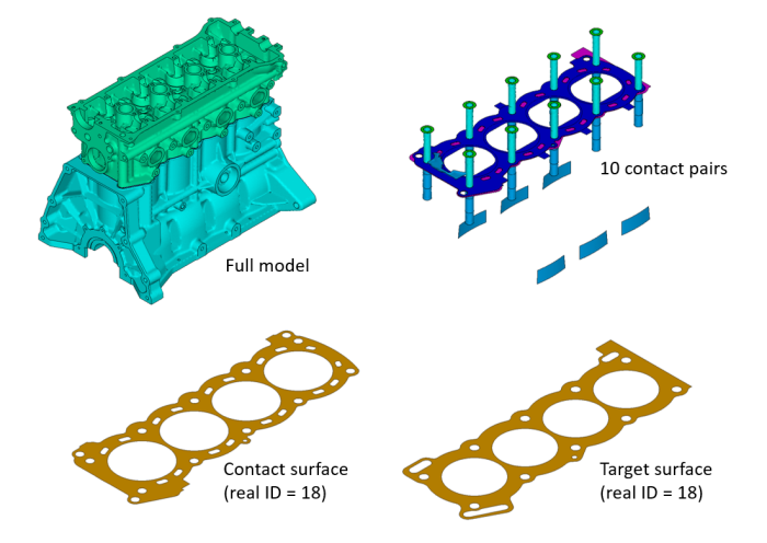
The following example demonstrates contact splitting for an engine block model. There are originally 10 symmetric pairs (real constant set IDs 14 to 23). The largest contact pair has real constant set ID = 18.
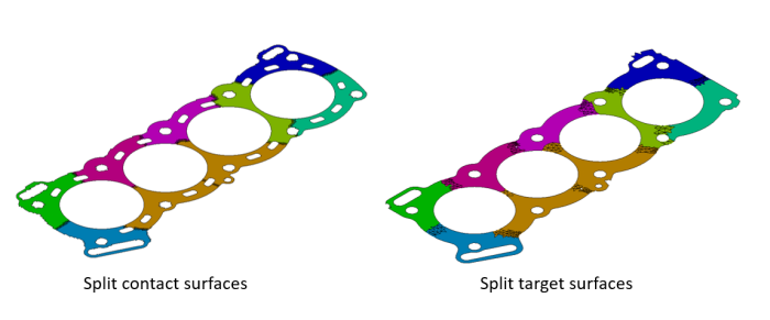
The command CNCHECK,DMP,,,,,9 activates the solution level splitting logic, which first removes the 5 companion pairs of the symmetric contact. Two large contact pairs among the remaining 5 are split. The largest contact pair (real constant set ID = 18) is split into nine smaller sub-pairs which have real constant IDs 18, 48, 49, 50, 51, 52, 53, 54, and 55.
Since small sliding contact pairs are defined, the split contact pairs are automatically trimmed by the CNCHECK,DMP command.
Example: Contact Pair-Splitting for Pairs with Disconnected Regions
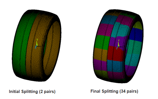
This tire is modeled as two disconnected regions (cut down the middle) that are included in one contact pair. Issuing the command CNCHECK,SPLIT or CNCHECK,DMP splits the two regions into two separate pairs first, and then does further splitting into 34 pairs total.
Use the TRlevel argument on the
CNCHECK command to define the maximum number of sub-pairs for
splitting the largest contact pair in the model. All smaller contact pairs will be
split proportionally based on this number.
The higher the number of CPU cores, the higher the
TRlevel value should be used. However, every
additional splitting attempt will add an extra target surface duplicated from the
original target surface. A higher sub-pair number increases overhead due to extra
communication among the split contact pairs.
Ansys, Inc. recommends a sub-pair number between 4 and 20. The general guideline is to use the smallest number to achieve an element load balance ratio below 1.5. The element load balance ratio is output right before the solution starts, for example:
     D I S T R I B U T E D   D O M A I N   D E C O M P O S E R
  ...Number of elements: 69763269
  ...Number of nodes:    281275836
  ...Decompose to 128 CPU domains
  ...Element load balance ratio =     1.002
If TRlevel is not specified, the program automatically
determines the maximum number of sub-pairs based on the ratio of contact elements of
the largest contact pair over the total number of elements in the model, and the
number of CPU cores used.
For contact splitting at the preprocessing level (Option =
SPLIT only), you can either define specific contact pairs through
RID1, RID2,
RINC and/or InterType as
follows:
If
RID1,RID2, andRINCare non-zero and positive, split the contact pairs from real constant pair ID numberRID1toRID2in increments ofRINC.You can also specify the type of contact pair to be split via
InterType. Only MPC-based contact pairs (InterType=MPC), bonded contact pairs (InterType=BOND), No separation contact pairs (InterType=NONS), and Small sliding contact pairs (InterType=SMAL) are allowed,You can even define
RID1,RID2, andRINCalong withInterTypeto narrow down the specific contact pairs to be split to contacts which belong to both the contact pair ID and type of contact pair.
For contact splitting at the solution level (Option = DMP
only), you can either define specific contact pairs through
InterType. Allowed contact pair types are:
MPC-based contact pairs (
InterType=MPC)Bonded contact pairs (
InterType=BOND)No separation contact pairs (
InterType=NONS)Small sliding contact pairs (
InterType=SMAL)
Two contact element real constants, BSRL and KSYM, play an important role in managing real constant set IDs for split contact pairs. Their meaning and usage are described here.
BSRL
Real Constants BSRL is generally the real constant set ID of the original contact pair before splitting. The program typically assigns this value to the sub-pairs during the splitting operation. BSRL can have other values as shown in the table below.
| BSRL = 0 (default) | Indicates the contact pair has not been split. |
| BSRL = positive number | This number equals the original real constant set ID and is set automatically by the split logic after contact pair-splitting. |
| BSRL = -1 | Indicates the contact pair will not be split (specified either by the program or by the user). |
During the split operation, the program automatically sets BSRL = -1 for contact pairs associated with the following feature which are not compatible with contact splitting:
| Wear analysis (TB,WEAR) |
| MPC surface-based constraints |
| Rigid-to-rigid contact |
| Impact constraints (KEYOPT(7) = 4 on the contact element) |
In addition, you can predefine BSRL = -1 for any contact pair that you do not want to split when CNCHECK,SPLIT or CNCHECK,DMP is issued. For example, you should always set BSRL = -1 for contact pairs that will have fluid penetration loading applied.
KSYM
The splitting logic supports rigid-flexible contact and flexible-flexible contact. It automatically deletes inactive contact pairs due to auto-asymmetric contact pair selection (KEYOPT(8) = 2 or 3).
For symmetric contact and self contact pairs, the program automatically sets KSYM during the splitting operation. For any symmetric contact pair, KSYM points to the real constant set ID of its companion pair. For self contact pairs, KSYM simply points to its own real constant set ID.
When a contact pair is split, the contact surface is automatically subdivided into several contact surfaces (sub-pairs) with different real constant set IDs based on the following logic:
The first sub-pair retains the same real constant set ID as the original base contact pair, including the entire original target surface. The program assigns this original real constant set ID to real constant BSRL of the sub-pair. Therefore, the BSRL value for the first sub-pair equals the real constant set ID of the original pair.
For the second sub-pair and beyond, the sub-pair is assigned a newly created real constant set ID. The newly created target surface for the sub-pair is simply a copy of the original target surface. For each sub-pair, the program assigns the original real constant set ID to real constant BSRL (that is, BSRL = the real constant set ID of the original contact pair before splitting).
Each split sub-pair uses real constants only from its original real constant set. Real constants of newly created real constant set IDs are ignored, except for BSRL and KSYM. Therefore, if you wish to change any contact properties for a split contact sub-pair (R or RMORE command), you need to modify the real constants of the original real constant set ID.
Important: You should not completely re-define the original real constant set after a splitting command is issued. Do not overwrite the real constants BSRL and KSYM of the original real constant set or of the newly created real constant sets defined by the splitting logic.
Use the ESEL command to select/unselect split contact
pairs. For example, this command selects split contact sub-pairs that are
associated with an original real constant set ID,
CID:
ESEL,S,REAL,BASE,CID
Select logic is useful for postprocessing contact results of an original contact pair.
Keep in mind that the contact merge logic is applied internally when contact results are stored in the results file (Jobname.rst). Therefore the results file only contains contact results which are mapped back to the original contact pairs, even though real constant sets of split pairs still exist. This is also true for the Jobname.cnd produced by the NLDIAG command. This file only lists contact diagnostic information for the original contact pairs. In addition, pair-based contact information can only be traced via the NLHIST command through original real constant set IDs.
Depending on which contact detection setting is used (KEYOPT(4) of the contact element), each contact surface of split sub-pairs may have overlapping layers of contact elements along the split boundaries. These overlapped contact elements are internally created during the splitting process and are used during solution to ensure the same overall solution results are obtained with or without contact pair-splitting. No actual contact results are computed for the overlapped elements.
If you decide to switch to a different contact detection method after CNCHECK,SPLIT has been issued, you should merge the contact pairs (CNCHECK,MERGE) and issue CNCHECK,SPLIT again.
If you add new elements after the CNCHECK,SPLIT command has been processed, make sure the newly created element numbers do not overwrite the numbers of any existing overlapped contact elements. To avoid this problem, it is strongly recommended that you issue the preprocessor-based splitting command right before the very first SOLVE command (that is, after the entire finite element model has been set up).
Use Item = OVER on the element selection command
(ESEL) to manage the overlapped contact elements created by
the splitting logic. For example, you may need to unselect the overlapped contact
elements during postprocessing to get averaged contact results based on the total
number of contact elements of the entire pair:
ESEL,U,OVER
The merging process (CNCHECK,MERGE) is the reverse of contact splitting. It simply combines the split contact pairs back to their original pairs.
You should always execute CNCHECK,MERGE before re-issuing the splitting logic for these cases:
If you modify the contact detection setting (KEYOPT(4) of the contact element).
If you readjust the maximum number of sub-pairs for splitting (increasing the number to reduce the element load balance ratio, or decreasing the number to reduce communication overhead due to a high number of splits).
The merge process only works on prior split pairs and performs the following steps:
Delete all overlapped contact elements.
Set the real constant set ID of all split contact elements (BSRL > 0) back to the original real constant set ID.
Delete all target elements which have a real constant value BSRL > 0.
Delete all real constant sets associated with real constant values BSRL > 0, except the original real constant sets.
Set all BSRL real constant values back to zero.
CNCHECK,MERGE is useful for postprocessing the contact results based on the original contact pair geometry. However, use caution when performing a downstream analysis since the merge operation may result in conflicts due to changes in the database.
The splitting logic subdivides large contact pairs into smaller split contact pairs and duplicates the original (base) target surface for every newly split pair, which adds many target elements. In many cases, trimming contact pairs is needed to reduce the overhead introduced by these additional target elements.
For the solver level splitting option (CNCHECK,DMP), the program
automatically deletes all inactive contact pairs defined from auto-asymmetric selection
(KEYOPT(8) = 2 or 3). It also trims target elements for the split contact
pairs that are associated with bonded contact (KEYOPT(12) = 5 or 6) or small sliding contact
(KEYOPT(18) = 1). By setting Val1
= TRIM on CNCHECK, the program automatically trims all split
contact pairs, regardless of the small or large deflection setting
(NLGEOM).
When splitting is invoked at the preprocessor level (CNCHECK,SPLIT),
the program only deletes inactive contact pairs. By setting
Val1 = TRIM on CNCHECK, the program
automatically trims all split contact pairs, regardless of the small or large deflection
setting (NLGEOM). You still have full control over which contact
pairs are trimmed after the splitting operation. To obtain the best solution performance,
you might consider using one or more of the following trim
operations:
CNCHECK,TRIM,,,,SMALL    ! Trim off all small sliding contact pairs
CNCHECK,TRIM,,,,BOND     ! Trim off all bonded contact pairs
CNCHECK,TRIM,,,,SELF     ! Trim off all self-contact pairs
In order to obtain the same results with and without splitting logic, the KEYOPT(8) = 3 setting for auto-asymmetric selection is preferred for the run with no splitting. With this setting the contact stiffness and other contact characteristics used for the active contact pair are completely independent of the inactive pair. It is as if the inactive pair does not exist.
The contact pair-splitting logic is applicable for most contact types. However, it automatically bypasses contact pairs in these categories:
Node-to-surface contact pairs (CONTA175)
General contact definitions
MPC surface-based constraints
Contact pairs that model contact surface wear with wear calculations based on the underlying element stresses (that is, TB,WEAR with
TBOPT= ARCD and C5 > 0 on the TBDATA command)Impact constraints (KEYOPT(7) = 4 of the contact element)
In addition, fluid penetration loading is not supported. Therefore, you need to set real constant BSRL = -1 for contact pairs that will have a fluid penetration load at some point it the analysis.
The splitting logic does not support the following analysis types:
Rezoning
Nonlinear mesh adaptivity with initial mesh-based loading and constraints. See Initial-Mesh Loading and Constraint in the Nonlinear Adaptivity Analysis Guide for more information.
2D to 3D analysis
Cyclic symmetric analysis
Solution Consistency
You may see differences in the solution results due to the following factors:
Operational randomness and numerical round-off can cause slightly different results between runs using different numbers of split pairs, and between runs on different numbers of cores. The difference is often negligible. However, in some cases the difference is appreciable. This is most commonly seen in nonlinear static or transient analyses that are numerically unstable (for examples, those that include buckling, rigid body motions, contact at corners, material softening, or interface debonding).
Due to the automatic or forced trimming logic, the total number of contact elements of any trimmed contact pair is usually less than the number of contact elements of its untrimmed original contact pair. Therefore, the pair-based contact characteristics (pinball, length, depth, contact stiffness) may not be exactly the same. As a result, slight solution differences will be obtained between the trimmed and untrimmed runs.


