


Although issuing multiple INISTATE,DEFINE commands is a valid way to assign explicit initial-state values to various items, it is faster and more efficient to create an external initial-state (.ist) file and read all of the data in at once (INISTATE,READ).
You can use an .ist file for either initial-state data-input method. The format of the file differs depending on the initial-state method used:
For the standard method of applying initial-state data, the following .ist file-format topics are available:
The .ist file supports element-integration-point-based data input or node-based data input (but not both at once).
The file format is comma-delimited ASCII, consisting of individual rows (lines) for each stress item. Each row consists of 10 columns separated by commas. Your columns delineate the integration point(s) for specific elements or nodes.
Element-integration-point-based data:
The element ID number
The element integration point (for standard elements)
The layer (for layered elements) or the cell number (for beams)
The section integration point (for beams and shells only)
The stress/strain/initial-state components
Node-based data (specify
/NODE,1before the data in the .ist file):
Node number
Element ID number
The layer number (for layered elements) or the cell number (for beam elements)
The section-integration point (for beam and shell elements only)
The stress/strain/initial-state components
The number of section-integration points for beams and shells depends on the associated user input. An element ID number can be repeated on successive rows to specify different stresses at different integration points.
For information about the number and location of available element integration points, see Integration Point Locations in the Theory Reference. For a listing of the integration points for each specific element, see Element Library in the Theory Reference.
Parameters for element ID, element-integration point, layer number, cell number, or section-integration point can be set to ALL in the .ist file.
You can provide additional data via attribute parameters
(/ATTR,VALUE line).
Supported parameters are /CSYS, /DTYP, and /NODE:
The default coordinate system is the global Cartesian system. Specify
/CSYS,VALUEto set the coordinate system to be used for the subsequent data provided in your .ist file.Apply initial strain by specifying
/DTYP,EPELbefore the initial-state/initial-strain data.To activate node-based initial state, specify
/node,1at the top of the initial-state input (.ist) file.
Example 4.5: Setting parameters
This input applies an equal stress of SX = 100 to all integration points or layers of the element ID = 1:
1,all,all,all, 100, 0, 0, 0, 0, 0
This input applies an equal stress of SX = 100 to all integration points or layers to all of the selected elements:
all,all,all,all, 100, 0, 0, 0, 0, 0
This input applies an initial strain of ex = 0.1 for all elements in the database.
/dtyp,epel all,all,all,all, 0.1, 0, 0, 0, 0, 0
To insert comments and other non-analysis information in the .ist file, precede them with an exclamation mark (!).
The mesh-independent method for applying initial state uses a special .ist data-file format that differs from that of the standard method.
The following .ist file-format topics are available for the mesh-independent method:
The .ist file format supports initial-state data types as a function of location and other solution variables. The data file must have a meta data section describing the data to be imported. Initial-state data types are the dependent variables, described as a function of independent variables.
The meta data section is followed by the data section, the components of which are comma-separated. The number of inputs in the data section must be equal to the sum of independent and dependent variables. The maximum number of independent variables is five.
The independent and dependent variables are described via /IDAT and /DDAT
commands. The ith variable is specified as:
/IDAT, |
| or |
/DDAT, |
Place the /CONT,ID command at the end of
each data section to save existing data and start a new set of
independent-dependent data for a different type (or for the same type).
ID is a unique integer from 1 to any number.
SubVariableIndex ranges from 1 to the maximum
allowed for the quantity or tensor. For example, for elastic strain, the range
can be from 1 to 6. UserLabel is any identifying
string that you wish to assign to the component.
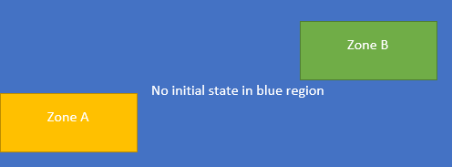
The /CONT command must separate the zones of mesh-independent data of the same type. When you have two zones of data, initial state is available only within the convex zones and any region outside of those zones will not have any initial state value. You can therefore apply multiple small zones of initial-state data without having to apply such data throughout the model:
Example 4.7: Applying Initial Elastic Strain as a Function of x and z
/idat,1,coor,1,x
/idat,2,coor,3,z
/ddat,1,epel,1,xx
/ddat,2,epel,2,yy
/ddat,3,epel,3,zz
/ddat,4,epel,4,xy
/ddat,5,epel,5,yz
/ddat,6,epel,6,xz
-1,0,1e-4,0,0,0,0,0
-1,1,1e-4,0,0,0,0,0
2,0,4e-4,0,0,0,0,0
2,1,4e-4,0,0,0,0,0
Additional attributes are specified in the meta data section of the
.ist file via the
/ATTRIB,VALUE command.
The only supported attribute is the /CSYS,CSID
command, enabling the dependent variables to be specified in a coordinate system
(CSID) other than global Cartesian. For example, if
initial stress is defined in a coordinate system other than global Cartesian,
the program interpolates the stress components in that coordinate system with no
transformation occurring when mapping to nodes or integration points. It then
applies the initial stress in the coordinate system defined via the /CSYS line
in the .ist file. Scalars such as user-defined field
variables are unaffected. Only Cartesian coordinate systems are supported for
this feature.
Example 4.8: Using the /CSYS Command Attribute in the .ist File
/com, This test demonstrates how /csys work in the ist file

local,11,0,,,,90
*create,data,ist
/csys,11
/dtyp,s
/idat,1,coor,1,X
/idat,2,coor,2,Y

/ddat,1,s,1,XX
/ddat,2,s,2,YY
/ddat,3,s,3,XY

! stress is defined in cs 11 as a function of global locations
0,0,1e-4,0,0
1,0,1e-4,0,0
0,1,3e-4,0,0
1,1,3e-4,0,0
*end


/prep7
et,1,182
keyo,1,1,1
keyo,1,3,2
csys,0
tb,elas,1
tbdat,,1e6,0.5

rect,0,1,0,1

lesiz,all,1,,
amesh,1

elist

/solu
inis,read,data,ist,,MAPI
/out
inis,list,all
inis,list,glob
allsel,all
d,all,all
solve

/post1
set,last
/out
/com, Interpolate stress is 2e-3 but rotated by 90 degress
presol,epel
presol,s

rsys,11
set,last
/out
/com,Use rsys command to rotate and verify
presol,epel
presol,s

fini
/exit
Independent variables:
COOR (with three subvariables) -- Subvariables can be 1, 2, or 3, corresponding to the X, Y, or Z directions, respectively, in the Cartesian coordinate systems. In a cylindrical coordinate system, the subvariables correspond to the radial, tangential, or normal directions, respectively.
TIME -- Time
TEMP -- Temperature
FREQ -- Frequency
Dependent variables:
STRE -- Initial stress
EPEL -- Initial elastic strain
UFXX -- user-defined field variables (such as UF01)
Elements:
Limitations:
Mesh-independent initial state cannot be used with any mesh-based initial state.
When applying the initial state and mapping to nodes internally (INISTATE,READ,,,,MAPN), the initial-state data saved to the nodal locations are written to the database.
Usage Notes:
When attempting to manually create a mesh-independent initial-state file (.ist) using results retrieved in a solution file (.rst), be aware that the nodal stress or strain results are available only at the corner nodes of any higher-order element.