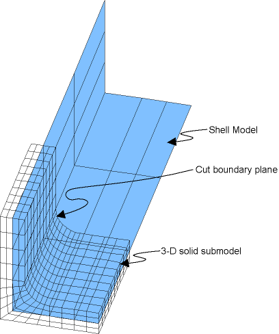
In the shell-to-solid submodeling technique, the coarse model is a shell model, and the submodel is a 3D solid model, as shown in this example:
The procedure for shell-to-solid submodeling is essentially the same as that for solid-to-solid submodeling, with these exceptions:
Shell-to-solid submodeling is activated by setting
KSHSto 1 on the CBDOF command () and the BFINT command (). This feature is not applicable to offsets used with SHELL181 (SECOFFSET), or SHELL281 (SECOFFSET).Cut boundaries on the submodel are the end planes that are normal to the shell plane (see Figure 7.13: Node Rotations). Nodes on these cut boundaries are written to the node file (NWRITE) ().
To determine the degree-of-freedom values at a cut-boundary node (CBDOF), the program first projects the node onto the nearest element in the shell plane. The degree-of-freedom values of this projected point are then calculated by interpolation and assigned to the corresponding node. Interpolated temperatures (BFINT) are calculated based on the average temperature at the midplane of the nearest shell element.
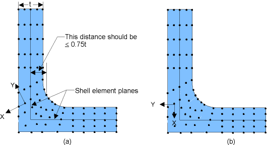
Note: The nodes on the cut boundary must lie within a distance of 0.75 times the average thickness of the nearest shell element, as shown in Figure 7.13: Node Rotations. That is, the submodel should be approximately centered on the coarse model.
In a structural analysis, only translational displacements are calculated for the cut-boundary nodes, but their values are based on both the translations and rotations of the projected point. Also, the node is rotated such that the nodal UY direction is always perpendicular to the shell plane, as shown in Figure 7.13: Node Rotations. A UY constraint is calculated only for nodes that are within 10 percent of the average shell element thickness from the shell plane, preventing overconstraint of the submodel in the transverse direction.
The .cbdo file written by the CBDOF command consists of two blocks:
The two blocks are separated by a /EOF command and a
:CBnn label (where nn is the cumulative iteration number of the results set used).
Because the two blocks of commands are separated by a /EOF command,
it is necessary to read in the .cbdo file twice. The second time
you read in the file, use the LINE field on
/INPUT ("Optional line number or label" in the GUI) to instruct
the program to read the file starting with the :CBnn label, as shown below:
/PREP7! The .cbdo file must be read in PREP7
/INPUT,,cbdo        ! Reads Jobname.cbdo up to the /EOF command
/INPUT,,cbdo,,:cb1  ! Reads same file from the label :cb1


