


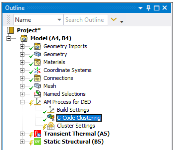
Controls element clustering using a G-Code file in a DED process simulation.
| Category | Description and Settings |
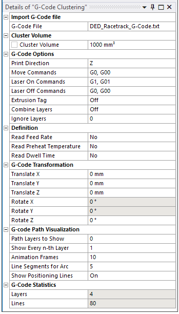
| Import G-Code File | Identification of G-Code file. |
| G-Code File: Name of the file containing the G-Code. The G-Code file must be a flat file with ASCII characters. | |
| Cluster Volume | Controls the size of the element clusters, and hence, has a direct influence on simulation time. |
| Cluster Volume: Volume, in mm3, of each cluster. This value determines how many elements are activated per load step, and the time for this load step is then determined by volume/deposition rate. A smaller cluster volume tends to provide a more accurate result. | |
| G-Code Options | Controls for interpreting the G-Code. |
| Print Direction: The direction of increasing layers in which the part is to be built. Choose X, Y, Z, -X, -Y, -Z, or 3D (Beta) for the print direction. Defaults to Z direction. Use 3D (Beta) for multi-axis machines. For information, refer to the Additive Manufacturing Beta Features document. | |
| Move Commands: Defines the G-Code commands for pure movement. Multiple commands can be specified using comma separation, such as G00, G01. | |
| Laser On Commands: Defines the G-Code command(s) for switching the laser to on (Laser On). All following move commands are used for element clustering until a Laser Off command is found. Multiple commands can be specified using comma separation, such as M24, M174. | |
| Laser Off Commands: Defines the G-Code command(s) for switching the laser to off (Laser Off). All following move commands are not used for element clustering until a Laser On command is found. Multiple commands can be specified using comma separation, such as M28, M175. | |
| Extrusion Tag: On/Off - G-Code commands may be extended by an extrusion tag “E.” This can be used to additionally control if material is deposited or not. With the Extrusion Tag option set to On, only commands with the “E”-tag are considered for subsequent element clustering. Default setting is Off. | |
| Combine Layers: On/Off - For multi-body parts, named selection folders from the different bodies that represent clusters at the same build-direction height can be combined. Useful for reducing the number of named selections but does not affect the element clustering itself. If Off (default), layers are not combined. | |
| Ignore Layers: Layers to be excluded from element clustering. Multiple layer numbers can be excluded using comma separated values. For example, 2,3 ignores the layers two and three from subsequent element clustering, so the clusters are divided into two instead of four layers. The default is 0, which includes all layers for element clustering (that is, 0 exclusions). | |
| Definition | Sets advanced controls for Feed Rate, Preheat Temperature, and Dwell Time. |
Read Feed
Rate: Yes or No. If Yes (default), feed rate commands
will be read from the G-Code file and used in the simulation.
| |
Read Preheat
Temperature: Yes or No. If Yes (default), preheat
temperature commands will be read from the G-Code file and used in
the simulation.
| |
Read Dwell
Time: Yes or No. If Yes (default), dwell time
commands will be read from the G-Code file and used in the simulation.
| |
| G-Code Transformation | The G-Code path must be correctly aligned on top of the build part to ensure proper element cluster generation. Use these translation and rotation offset options to position the G-Code path in relation to the build part, if necessary. Rotation is allowed only in the printing direction, so once the Print Direction field is specified, the rotation options for directions other than Print Direction are grayed out. See more details about G-Code alignment. |
| Translate X: Defines the offset in the print direction with respect to the actual X, Y, or Z positions defined in the G-Code file. | |
| Translate Y: Offset in the Y direction. | |
| Translate Z: Offset in the Z direction. | |
| Rotate X: Defines the rotation about the X axis positions defined in the G-Code file. Rotation is only allowed in the printing direction. | |
| Rotate Y: Defines the rotation about the Y axis positions defined in the G-Code file. Rotation is only allowed in the printing direction | |
| Rotate Z: Defines the rotation about the Z axis positions defined in the G-Code file. Rotation is only allowed in the printing direction | |
| G-Code Path Visualization | Controls the appearance of the G-Code path
in the geometry window when the Show Path button |
| Path Layers to Show: Path layers from the G-Code file to display. Enter a range of values with a hyphen and multiple values separated by commas. For example, 1-10, 25-30 displays layers 1 through 10 and 25 through 30. The value 0 displays all layers and is the default setting. | |
| Show Every n-th Layer: Displays every n-th path layer of the designated Path Layers to Show. For example, the value 2 displays every second layer, 3 displays every third layer, and so on. The value 1 displays all layers designated in Path Layers to Show and is the default setting. | |
| Animation
Frames: Animation frames in which the designated Path
Layers to Show are rendered. Click the Show Path button
| |
| Line Segments for Arc: The graphical display of an arc path is approximated by a number of lines in the geometry window. The number of lines per arc can be modified, a useful option for G-Code files with many arcs in order to speed up the graphical display. The default number of line segments is 5. | |
| Show Positioning Lines: On/Off - On (default) displays the rapid movement commands in the G-Code. Off suppresses the display of rapid movement commands. | |
| G-Code Statistics | Read-only indications after generation of element clusters. |
| Layers: After generation of element clusters, shows the number of path layers in the part. This number includes the rapid movements without material deposition. | |
| Lines: After generation of element clusters, shows the number of lines in the weld path. |
Valid Parent Tree Object: AM Process for DED
Valid Child Tree Objects: None
Inserted under the AM Process for DED object in the project tree automatically by the DED Process Wizard if G-Code is selected.
Select the DED Process tab and then click the G-Code Clustering button in the ribbon.
Relevant right-click options include:
Generate: Generates the element clusters using the path defined in the G-Code file.
Clear Generated Data: Clears any generated clusters.
Show G-Code Path: Displays the G-Code path on the geometry.
Clear G-Code Path: Hides the display of the G-Code path on the geometry.