


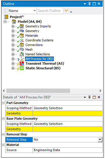
Identifies the geometries, source of material data, and base removal options in a DED process simulation. Also sets global options for all AM-related objects.
| Category | Description and Settings |
| Build Geometry | The part to be printed. |
| Scoping Method: Choose Geometry Selection or Named Selection to identify the part geometry. | |
| Base Plate Geometry | The base plate upon which the part rests. |
| Scoping Method: Choose Geometry Selection or Named Selection to identify the base plate geometry. | |
| Removal Step | Should the simulation include the removal of the part from the base plate? |
| Removal Step: No/Yes - If No
(default), simulation does not include the removal of the part from
the baseplate. If Yes, simulation includes the removal of the part from the base plate. Scoping Method: Choose Geometry Selection or Named Selection to identify the base plate geometry. | |
| Material | The deposition material. |
| Source:
Engineering Data/Input file - Choose Engineering Data to use a
predefined material. Or choose Input file and then specify Input File Print Material and Input File Base Material. Files must be in ASCII format with a.inp extension. |
Valid Parent Tree Object: Model
Valid Child Tree Objects: Build Settings, G-Code Clustering, Manual Clustering
Inserted under the Model object in the project tree by default when using the DED Process Wizard.
Select the DED Process tab and then click the DED Process button in the ribbon.
Relevant right-click options include:
Generate: Generates element clusters using the path defined in either the Manual Clustering or G-Code Clustering child object.
Clear Generated Data: Clears clusters that have already been generated.