


To establish the options and assumptions appropriate for a DED process simulation, you need to insert the AM Process for DED object into the project tree. Here you will identify which bodies are associated with the build and the base plate.
Procedural Steps
Select the DED Process tab on the ribbon and then click the DED Process option from the DED Process tool bar. Notice that the AM Process for DED object is added to the project tree.
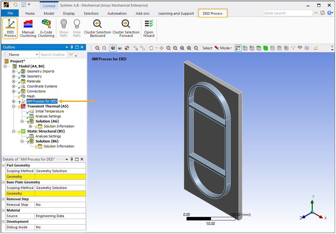
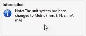
Also, the unit system is checked automatically and, if necessary, changed to the Metric system (mm, t, N, s, mV, mA) since the DED Process Add-on requires that units be in millimeters. The following message appears if the unit system is changed:
Next you need to identify which bodies are which in the geometry you imported. Select the AM Process for DED object and then:
Select the body or bodies representing the part that make up the Build Geometry and click Apply in the Details view under Build Geometry. To select a body, be sure that your mode of selection is on body
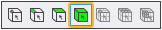 (rather than on face,
edge, or vertex). Use the Ctrl key while clicking the left mouse button
to select multiple entities (or click, hold, and drag). Or use named
selections as a basis for selection. When selected, the build geometry
is shown in green. Clicking Apply displays the build geometry in blue.
(rather than on face,
edge, or vertex). Use the Ctrl key while clicking the left mouse button
to select multiple entities (or click, hold, and drag). Or use named
selections as a basis for selection. When selected, the build geometry
is shown in green. Clicking Apply displays the build geometry in blue. 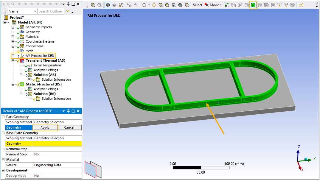
Select the body that is the Base Plate Geometry and click Apply in the Details view. (If your imported geometry does not have a base plate, construct one in the next step.)
To create the base plate if not imported with the CAD geometry, select the Model object and then:
Right-click the Model object or in the geometry window and select Insert > Construction Geometry.
Right-click the new Construction Geometry object (under Model) and choose Insert > Solid.
In the Details view, fields appear for you to enter coordinates with respect to the center of the top of the base. Enter values for X1, X2, Y1, Y2, Z1 and Z2. An outline is provided to preview the dimensions. Right-click Solid and select Add to Geometry. For more information, see Construction Geometry in the Mechanical User's Guide.
To identify this newly created body as the Base Plate Geometry, highlight the DED Process object, select the new body and click Apply in the Details view for Base Plate Geometry.