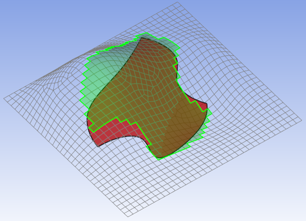
The Geometrical Selection Rule allows you to define the extent of a modeling ply or OSS based on a CAD surface or solid geometry. Elements are selected if they lie within the enclosure of a defined volume. The volume is set by the size of the CAD solid geometry or the CAD surface geometry in combination with specified Capture Tolerances. This means that a flat CAD surface geometry can be used to define a ply on a curved mesh surface. Figure 2.61: Example Geometrical Selection Rule shows a selection inside a curved mesh enclosed by a flat surface with relatively high negative and positive capture tolerances. See CAD Geometries for information on how working with geometries impacts system performance.
Geometrical Selection Rules have the following settings:
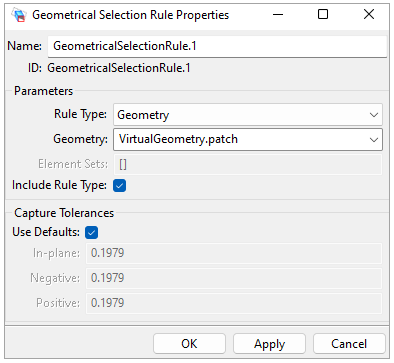
Rule Type: Define whether the rule extent is defined by a geometry of Element Sets. The value can be geometry or element_sets. The default is setting is geometry.
Geometry: Virtual Geometry defining the basic selection (only relevant for Rule Type: Geometry).
Geometry:
defining the basic selection (only relevant for Rule Type: Geometry).
Element Sets: Preselection of elements in the form of an Element Set where the rule is applied on (only relevant for Rule Type: Element Sets). Multiple Element Sets can be parsed as input by holding the [Ctrl] button while making your selections.
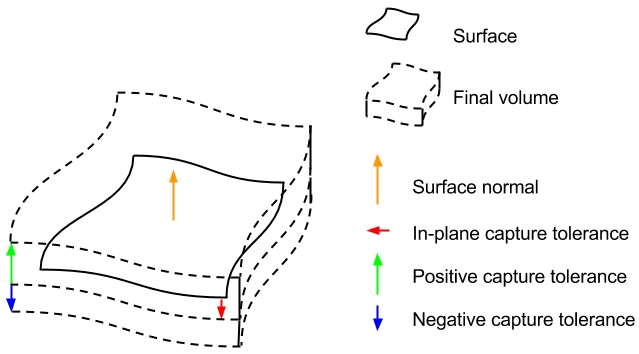
Capture tolerances are necessary for non-solid geometries, such as surfaces. They evaluate whether a point is within the geometry by creating an envelope as shown below. The unit values are in length. All three tolerances support negative values.
Use Defaults: Defines if the default value is used. The default value is the Offset property of the CAD geometry.
In-plane: Increase the in-plane extension of the geometry by this value. A negative value will shrink the surface.
Negative: Capture tolerance in the reverse direction of the surface normal. A negative value offsets the geometry in the surface normal direction.
Positive: Capture tolerance in the direction of the surface normal. A negative value offsets the geometry in the opposite direction of the surface normal.
The in-plane tolerance can also be adjusted on the Modeling Ply level by template rule parameters. This may be useful when defining ply tapering. For more information, see Selection Rules.
Note: In principle, the in-plane tolerance is used to extend to the boundary of the geometry. It is also used to fill gaps between adjacent surfaces that may cause sampling issues. Therefore, it is recommended to use an In-plane tolerance > 0 when the selection is missing some elements inside the capturing geometry.