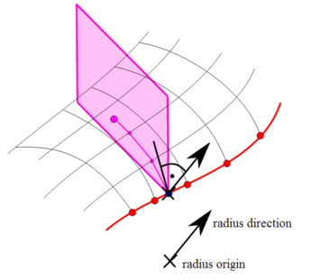
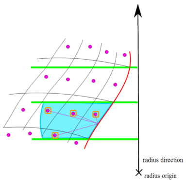
The Variable Offset Selection Rule is defined on the basis of an Edge Set and a 1-D Look-Up Table containing a list of offsets at different locations. Elements adjacent to the Edge Set are selected if their centroids lie within the specified offset at the given locations. The offsets are linearly interpolated between locations. In this way, the rule behaves like an advanced Tube Selection Rule where the outer radius can be varied.
There are two different ways in which the Look-Up Table data can be interpreted: the location of each offset can be mapped on to a direction vector (default), or on to the length of the Edge Set.
The rule is not called the variable radii rule is because you can deifine the offset over a curved surface defined by an Element Set. The offsets are initially evaluated as a radius at each element adjacent to the Edge Set. The Offset Correction then adjusts the offset so that the offset is measured over the curvature of the surface.
The template rule functionality is not available for the Variable Offset Selection Rule; however there is a way to accommodate ply staggering with this rule. In addition to the offsets, varying ply taper angles can also be defined in the form of a 1-D Look-Up Table. Ply Tapering can be used when multiple Modeling Plies share the same Variable Offset Selection Rule. In such cases, the first Modeling Ply will cover the area defined by the offset definition. The subsequent plies will be tapered based on the angle definition. The tapering is applied not on the Edge Set side, but on the offset side, away from the Edge set.
Note: The angle definition can be used to decrease, fix, or increase the covered areas of the subsequent Modeling Plies.
Complex patch shapes can be realized with the help of this selection rule.
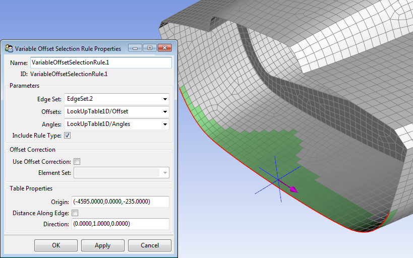
- Parameters
Edge Set: The offsets are measured along this Edge Set.
Offsets: 1-D Look-Up Table with a list of offsets at different locations.
Angles: (optional) 1-D Look-Up Table with a list of angles at different locations. Only active when same rule is applied to multiple Modeling Plies. Does not affect the first Modeling Ply. Depending on the local angle, the covered area of the subsequent plies is changed.
Angle equals 90 deg: Plies are not changed.
Angle less than 90 deg: Ply coverage decreases with number of modeling plies.
Angle greater than 90 deg: Ply coverage increases with number of modeling plies.
Include Rule Type: The selection envelope can be inverted with this option.
- Offset Correction
Use Offset Correction: The offset is measured along the surface curvature of the selected Element Set in a segmented arc when this option is active.
Element Set: The offset correction is calculated on the curvature of this Element Set. The selection rule can be applied to other Element Sets also, but retains the offset correction.
- Table Properties
Origin: This replaces the origin in the 1-D Look-Up Table definition.
Direction: This replaces the direction in the 1-D Look-Up Table definition.
Distance Along Edge: When active, the 1-D Look-Up Table data is mapped along the distance of the Edge Set. In this case, the origin is used to determine the start and the end of the Edge Set. The mapping will start at the corner of the edge which is closest to the origin. The zero location in the Look-Up Table coincides with the start of the selection rule.