A Cut-Off Selection Rule acts as a cutting operation on the composite lay-up. In contrast to other Selection Rules that affect the in-plane directions of the ply, a Cut-Off Selection Rule also considers the laminate thickness. A Cut-Off Selection Rule can be defined by a geometry or a taper. Using a Geometry Cut-Off Selection Rule, the ply is cut at the intersection with a CAD Geometry, taking into account the thickness of the laminate. An example of this is a skew-whiff surface being used to define the tapering near a trailing edge of a blade. A Taper Cut-Off Selection Rule cuts plies based on an edge and a taper angle.
Only Analysis Plies are cut off as a result of the selection rule. Modeling and Production Plies are not affected. The Cut-Off Selection Rule is similar to a milling operation on built-up structure. In that sense, the full size Modeling and Production Plies are required before the machining operation. The Analysis Plies are the only decisive plies for any structural computation.
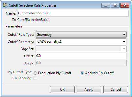
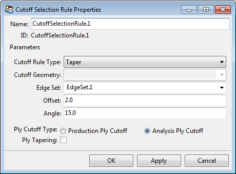
Cut-Off Selection Rule settings are:
Name: Name of the Selection Rule.
Cut-Off Geometry: The CAD geometry defining the Cut-Off.
Offset: CAD / taper surface offset. The intersection of the CAD Geometry/taper edge and the lay-up can be moved by an offset. The direction and orientation of the offset is defined by the normal direction of the Oriented Selection Set.
Edge Set: Selection of an Edge Set (Taper).
Angle: Taper angle (Taper).
Ply Cut-Off Type: Either the complete production ply is cut off or individual analysis plies are cut off. Ply Tapering can only be activated in the latter case.
Ply Tapering: Control of the Cut-Off resolution.
For each element, ACP determines the position of the ply (including its offset) in relation to the imported surface. There are two possibilities of how the model geometry is cut by a CAD geometry - one cutting operation follows the geometry contour, the other divides the ply into either its maximum thickness or zero thickness. This is controlled by the Ply Tapering option in the Cut-Off Selection Rule Properties dialog.
In the first method, the ply is cropped if it intersects with the geometry. The ply is cut to match the external geometry.
In the second method, the ply is cut at a discrete point. The ply cannot have a varying thickness - it is either at its maximum thickness or it has been entirely cut off. The ply is cut if the intersection of CAD geometry and ply is less than half of the ply's thickness.
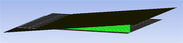
The following figures are taken from Tutorial 4 and are presented to explain the concept further. In the tutorial, a Geometry Cut-Off Selection Rule is applied to the core. A section view of the Cut-Off Geometry, applied to two edges, is shown in the figure below. The Cut-Off has a nominal thickness of approximately two thirds of the core thickness and, towards the outside, it has a multi radii edge. The dashed yellow line in the figure denotes the ply's centerline.

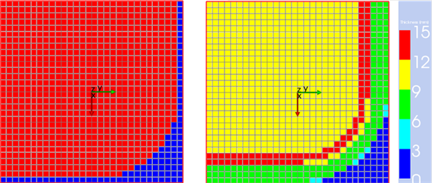
When Ply Tapering is activated, the core is cropped to match the Cut-Off Contour, as shown in the right figure below. If Ply Tapering is deactivated, the resulting core thickness is at its full thickness everywhere the intersection of the geometry is above the core centerline. Everywhere else, the core is completely cut off.
The second way of using the Cut-Off Selection Rule is to define a taper with an Edge Set and a tapering angle. The area close to the edge has to be sufficiently meshed for the taper Cut-Off to work. Similar to the Geometry Cut-Off, the ply is cut off in the taper zone. Only if Ply Tapering is selected will there a be a gradual taper over thickness. The Taper Cut-Off Selection Rule allows the same definition as the Taper Edges feature for modeling plies. For a detailed explanation of taper angle and offset, see Edge Tapering.
By default, ACP analyzes the Cut-Off selection rule at the element centers. Each element is cropped from the ply if the ply thickness at the element center is negative. This binary representation may not be sufficiently accurate in certain cases. If the Use Nodal Thickness is enabled, the Cut-Off and ply tapering (if enabled) will be refined, which in turn results in a more accurate model. For more information, see Element- vs. Node-based Thicknesses.
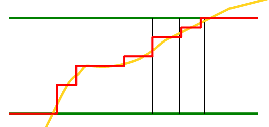
Consider a Stackup of three Fabrics for this example. In the pictures below, a laminate of one Stackup is shown marked with the green lines. The blue lines highlight the Analysis Plies of the Stackup. The black lines represents the mesh and the red line indicates the final laminate resulting from the Cut-Off Selection Rule.
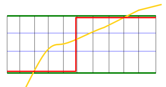
The Cut-Off Selection Rule with the Analysis Ply Cut-Off option will result in a smoother section as each Analysis Ply of the Stackup is cut individually.
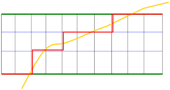
The Cut-Off Selection Rule with Ply Tapering will result in an even smoother section. The ratio between the area of the section cut by the CAD Geometry and the uncut section is calculated. The same ratio is applied to the ply thickness for the considered element.