The section cut feature implements the computation of the equivalent sectional properties. You can use sectional properties to model slender structures, such as wind turbine blades or helicopter blades, with beam elements. This significantly improves the efficiency of analyses, especially non-linear or transient analyses. The computed values can be used in combination with the preintegrated composite beam section of Mechanical APDL (see Using Preintegrated Composite Beam Sections in the Structural Analysis Guide) and element types BEAM188 and BEAM189.
The computation can be run either by the Python shell of ACP or context menu of the Section Cut. Select the Compute Equivalent Beam Properties... item to open the analysis dialog.
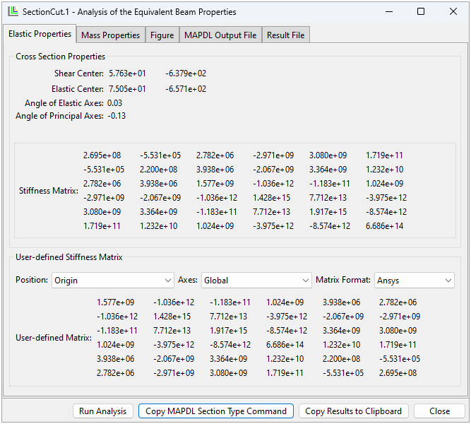
Figure 2.114: Elastic Properties after Running Analysis of the Sectional Properties (via Run Analysis Button)

The dialog contains the following buttons:
Run Analysis: Generate the input file for the Mechanical APDL solution, run the analysis, parse the results, and update the figure.
Copy MAPDL Section Type: Convert the stiffness and mass matrix into the Mechanical APDL SECTYPE command for a preintegrated composite beam and copy it to the clipboard. The command (string) can be used in Mechanical APDL or Mechanical via a command snippet to define the properties of beam elements.
Copy Results to Clipboard: Copy all elastic and mass properties to the clipboard.
Close: Close the dialog. Note that the results are not saved.
The sectional properties are computed with respect to the section cut's coordinate system that is defined by the origin, normal, and first reference direction of the section cut. The results are shown at the top of the Elastic Properties and Mass Properties tabs.
Both tabs have a user-defined section to convert the matrix with respect to the Position and Axes system. You can use the Matrix Format to order the entries of the matrices for the corresponding application. The computed matrices can be used in combination with the preintegrated composite beam section of Mechanical APDL (see Using Preintegrated Composite Beam Sections in the Structural Analysis Guide), if the Format is set to Ansys. For more information about the format of the stiffness and material matrix, see the Theory section.
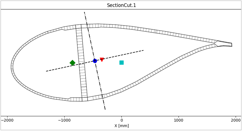
The Figure tab shows the section cut mesh and the positions of the shear center, CoG, and elastic center with respect to the section cut's origin.
In case of errors, use the MAPDL Output File and Result File to investigate the analysis.
The computation is based on the theories of [Giavotto et al. (1983)] and [Ghiringhelli et al. (1994)].
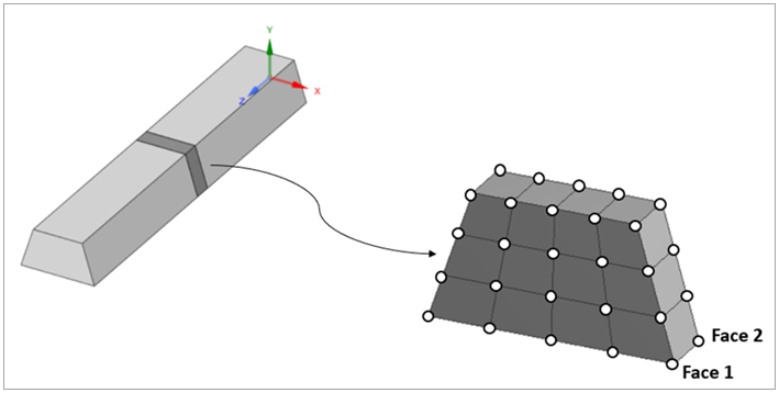
A 3D mesh slice (SOLID186 element) of the beam section is generated using section cuts, as represented in the figure below. The computational model of the section cut is automatically converted to the reference coordinate system, where x and y are the beam section in-plane axes, while the beam longitudinal axis follows the global z (positive).
The global FE stiffness and mass matrix of the slice are then computed using the Mechanical APDL Solver.
The global mass matrix is used to compute the equivalent beam mass matrix per unit length.
The global stiffness matrix is used as the starting point to
compute all the matrices required by the theory
explained in [Giavotto et al. (1983)].
The global stiffness matrix is split into four submatrices (the subscripts 1 and 2 refer to face-1 and face-2 of the solid slice):
These four K-sub-matrices are then combined following the implementation explained in [Ghiringhelli et al. (1994)] to build the system of equations of [Giavotto et al. (1983)], solve them, and finally compute the stiffness matrix of the beam section.
The results of the computation are the stiffness matrix of the cross section, mass matrix, and other section properties such as shear center and center of gravity. The primary results are with respect to the origin of the section cut and the global coordinate system of the section cut which is defined by the normal and reference direction 1.
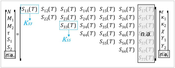
The standard output stiffness matrix produced by this feature has the following form:
where,
and
are the shear forces along the x and y directions
is the force along the beam longitudinal axis (axial force)
and
are the bending moments around the x and y axes
is the torsional moment around the beam axis
and
are the transverse shear strains
is the axial strain
and
are the curvatures in the x and y axes
is the twist
All the represent a stiffness value. The
ones on the main diagonal are:
| Shear stiffness in x plane | |
| Shear stiffness in y plane | |
| Axial stiffness | |
| Bending stiffness in x plane | |
| Bending stiffness in y plane | |
| Torsional stiffness |
This feature also computes the following important quantities:
Elastic center coordinates
Shear center coordinates
Center of gravity coordinates
Angle of the elastic axes
Angle of the barycentric principal axes
The results of the computation are the stiffness matrix of the cross section, mass matrix, and other section properties such as shear center and center of gravity.
You can request for the stiffness and mass matrix to
be printed out and reordered to follow the specific
Ansys beam section type form
SECTYPE,,COMB,MATRIX, which can
be used to assign the computed equivalent beam
properties to an Ansys beam element (such as
BEAM188 or
BEAM189). See the
get_transformed_sectional_properties_matrix()
function of the Section Cut. There is an example at
the end of this section which generates an input
file for Mechanical APDL.
The
get_sectional_stiffness_behavior()
extracts the equivalent stiffness values from the
matrix.
Reordering Example
The value in the standard output becomes the
value in position (1,1) of the
SECTYPE,,COMB,MATRIX, while the
value
becomes the value in position
(3,3).

For a detailed description of the stiffness and mass matrix form in this case, see Using Preintegrated Composite Beam Sections in the Structural Analysis Guide.
The position and orientation of the section cut are important. Typically, the section cut plane is perpendicular to the mesh and the origin is placed in the center of the mesh. The section cut provides methods to transform points from the global coordinate system to the coordinate system of the section cut, and vice versa.
Export Section Cut Example
Export section cut properties to Mechanical APDL as a preintegrated composite beam.
model = db.active_model
model.update()

with open("D:\\tmp\\composite_sections.cdb", "w") as mapdl_file:
    for index, sc in enumerate(model.section_cuts.values()):
        # compute equivalent beam properties
        results = sc.compute_equivalent_beam_properties(check_status=True)
        sectype_command = sc.get_sectype_command_from_sectional_properties(
            properties=results.properties,
            stiffness_matrix_position="elastic center",
            stiffness_matrix_angle="elastic axes",
            mass_matrix_position="center of gravity",
            mass_matrix_angle="principal axes",
            sectype_id=index+1
        )
        mapdl_file.write(sectype_command)
This feature has the following limitations:
The computation becomes expensive (RAM and time) if the section cut has many nodes (over 5000). The number of nodes can be reduced by combining plies with equal material and orientations.
The default properties of variable materials are used for the calculation of the equivalent beam properties. For instance, the effect of draping is ignored if material properties vary with respect to the shear angle.
The computation of the respective sectional properties based on Ghiringhelli's theory (see [Ghiringhelli et al. (1994)]) was compared with that of Becas. The comparison contains various cross sections with different materials and layups, and the results are almost identical.


