


Section Cuts enable a visual verification of the lay-up definition on an arbitrary section plane through the model. The lay-up definition at the Section Cut can be exported to Mechanical APDL or BECAS.
The Section Cut Properties dialog contains the following options:

Name: Name of the Section Cut.
Active: Set to false to suppress the computation of the Section Cut.
Interactive Plane: If active, modify the section plane directly in the Scene. If inactive, the following options are required:
Origin: Origin of the section plane.
Normal: Normal direction of the section plane.
Reference Direction 1: First in-plane reference direction (in-plane transverse direction). The normal and this direction define the coordinate system of the section cut. It is used to compute the section cut measures and to export the surface section cut.
Show Plane: Plot the section plane.
Entire Model: If active, the Section Cut applies to all shell elements in the model. Otherwise, only the selected Element Sets are considered.
Element Sets: List of Element Sets to which the Section Cut is scoped.
Type: Mode of extrusion.
Scale Factor: Scale the offsets of all plies.
Core Scale Factor: Thickness of the core plies are scaled by this factor.
Section Cut Type: Select which ply type is plotted:
Modeling Ply Wise: Modeling Plies are plotted.
Production Ply Wise: Production Plies are plotted.
Analysis Ply Wise: Analysis plies are plotted.
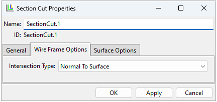
Interaction Type: Define the intersection of the section plane and the model:
Normal to Surface: Plies are plotted as normal to the intersected elements.
In Plane: Plies are plotted in the section plane.

Use Default Tolerance: Use the default tolerance (0.1% of the average element size). If unselected, you should specify the Tolerance:
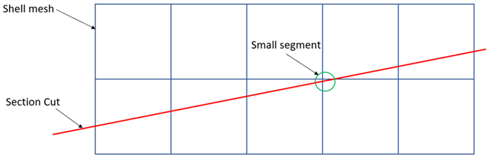
Tolerance: Defines the minimum length of the line segments in a Section Cut. Segments shorter than the tolerance are merged. Small segments can occur if a Section Cut crosses an element corner as shown below. In some cases, the Section Cut can be relocated to avoid small segments.
Sweep based extrusion:
Use Default Interpolation Settings: Use default interpolation settings. If unselected, you must specify Search Radius and Number of Interpolation Points. For more information, see 3D Look-Up Table.