


In this section, you will create a composite model, extrude it into a solid structure, then assemble the structure with the provided metal parts.
The following steps will guide you through creating a composite model in ACP (Pre):
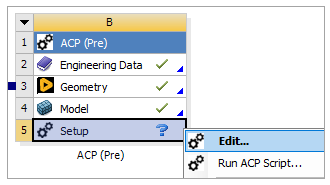
Right-click the Setup cell in the ACP (Pre) system and select Edit to open ACP.
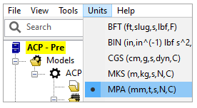
In ACP, select Units from the menu and select MPA (mm,t,s,N,C).
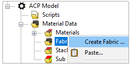
In the Tree View, expand Material Data. Right-click Fabrics and select Create Fabric.
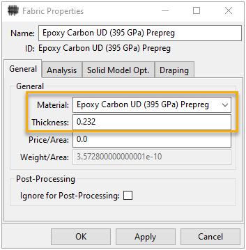
Define the fabric using the Material and Thickness as shown in the image below. Click Apply, then click OK.
In the earlier tutorials, you learned that Rosettes set the directions for Oriented Selection Sets (OSS) and OSSs define the basis for a composite model's lay-up. In this section, you will create an Edge Wise Rosette and an OSS.
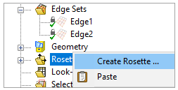
In the Tree View, right-click Rosettes and select Create Rosette.
In the Rosette Properties dialog, select Edge Wise from the Type drop-down menu (A, below). For the Edge Set, select Edge1 from the drop-down menu (B). Keep the other properties as default.
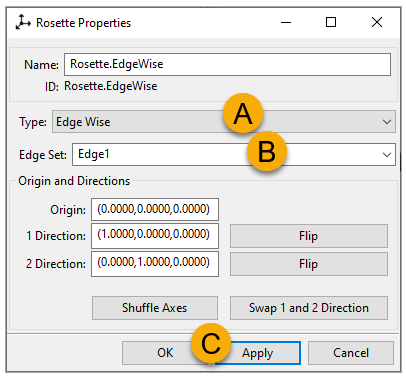
Click Apply (C, above) then close the dialog. The Rosette is now visible in your model.
Note: For an Edge Wise Rosette, the X direction (1 Direction) is projected on to the point on the Edge that is closest to the origin of the Rosette. When you define an OSS using this Rosette, the OSS' Reference Direction is determined along the Edge Set.
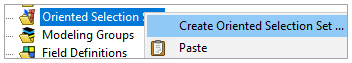
In the Tree View, right-click Oriented Selection Sets and select Create Oriented Selection Set.
In the Oriented Selection Set Properties dialog, place the cursor in the Element Sets field (A, below), then select All_Elements from Element Sets in the Tree View (B).
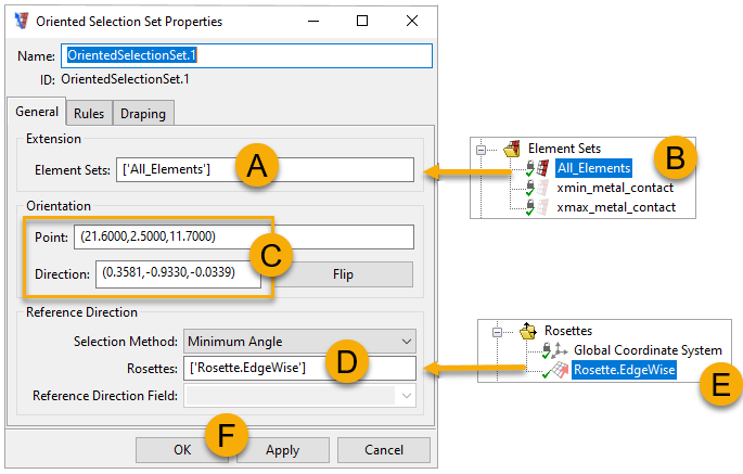
The Orientation Point defines the model's reference surface on which the plies are applied. Define it by clicking the Orientation Point field and selecting any element on the reference surface (C, above). The Orientation Direction, a vector defining the normal direction at the Orientation Point, will be defined automatically.
Place the cursor in the Rosette field (D, above) and select Rosette.EdgeWise from Rosettes in the Tree View (E). Click Apply (F), then close the dialog.
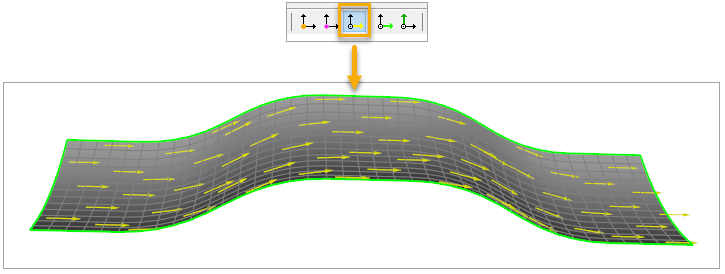
Enable the Show Reference Direction icon on the toolbar to view the OSS' Reference Direction.
Follow these steps to create the plies for the composite model:
In the Tree View, right-click Modeling Groups and select Create Modeling Group (A, below). In the Modeling Group Properties dialog, name the Group
PlyGroup.1(B). Click Apply, then close the dialog.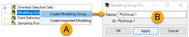
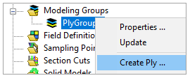
Right-click the newly created PlyGroup.1 in the Tree View, then select Create Ply.
In the Modeling Ply Properties dialog, place the cursor in the Oriented Selection Sets field (A, below), then select OrientedSelectionSet.1 under Oriented Selection Sets in the Tree View.
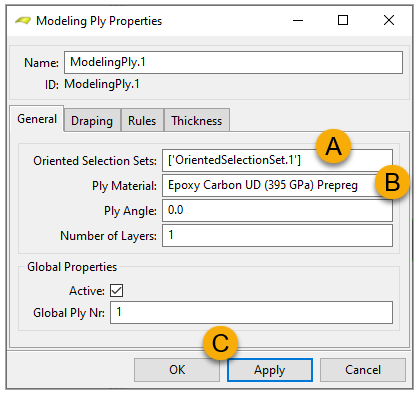
Select Epoxy Carbon UD (395 GPa) Prepreg from the Ply Material drop-down menu. Leave the other properties as default. Click Apply (C), then close the dialog.
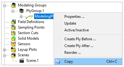
In the Tree View, right-click ModelingPly.1 and select Copy (or press Ctr+C).
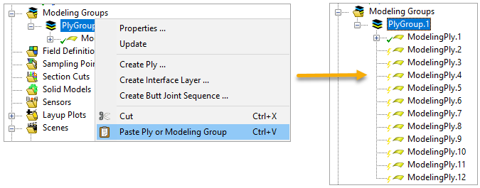
Right-click PlyGroup.1 and select Paste (or press Ctr+V) 11 times to have a total of 12 plies.
From the toolbar, click the Edit Entities with Excel icon.

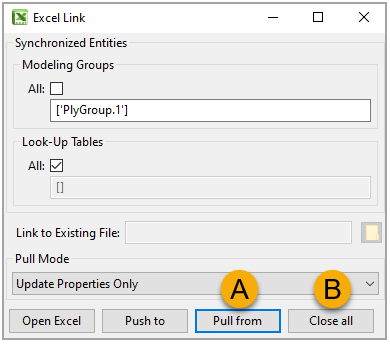
In the Excel Link dialog, specify Modeling Groups by deselecting All. Place the cursor in the field (A, below), and select PlyGroup.1 from Modeling Groups in the Tree View.
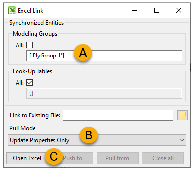
Under Pull Mode, select Update Properties Only (B, above). Click Open Excel (C).
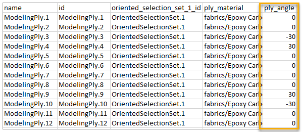
When Excel has launched, modify the ply_angle column as shown in the image below.
In the ACP's Excel Link dialog, click Pull from (A, below), then click Close all (B).
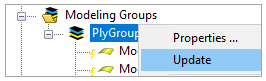
Under Modeling Groups, right-click PlyGroup.1 and click Update to finish creating the plies.
Close the ACP window and go back to Workbench.
In this section, you will import a CAD geometry into ACP to extrude the composite model into a solid structure.
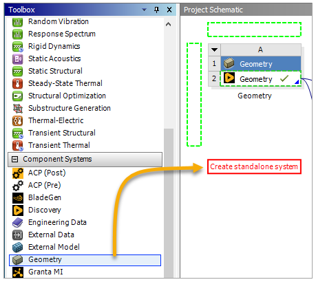
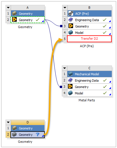
In Workbench's toolbar, under Component System, click Geometry and drop it into the Project Schematic pane.
Click the D2 Geometry cell and drop it onto the B5 Setup cell to connect the two cells. This particular geometry component is used for editing the definition of the Solid Model and is not the primary geometry of the composite structure.
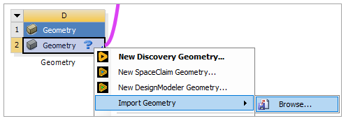
Right-click Geometry, select Import Geometry, then select Browse. Choose the extrusion_guide.stp file from the project folder.
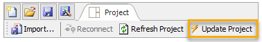
Click Update Project on the toolbar.
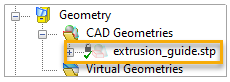
Open ACP again. In the Tree View, expand Geometry and CAD Geometries. You can see that extrusion_guide.stp is automatically imported into ACP.
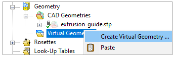
Under Geometry, right-click Virtual Geometries and select Create Virtual Geometry.
In the Virtual Geometry Properties dialog, change the Name to
CADGeometry.1(A, below). Place the cursor in the Sub Shapes field (B), then select the extrusion_guide.stp CAD geometry from the Tree View.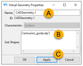
Click Apply (C, above), then close the dialog. The virtual geometry is now visible in your model.
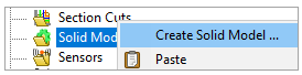
In the Tree View, right-click Solid Models, then select Create Solid Model.
In the Solid Model Properties dialog, place the cursor in the Element Sets field, then select All_Elements from Element Sets in the Tree View. Keep the other properties as default. Click Apply, then close the dialog.

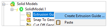
In the Tree View, expand Solid Models and Solid Model.1. Right-click Extrusion Guides, then select Create Extrusion Guide.
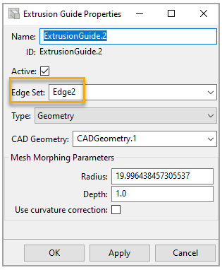
In the Extrusion Guide Properties, select Edge1 from the Edge Set drop-down menu (A, below). Select Geometry from the Type drop-down menu (B).

Select CADGeometry.1 from the CAD Geometry drop-down menu (C, above). Click Apply (D), then close the dialog to finish creating the first Extrusion Guide.
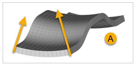
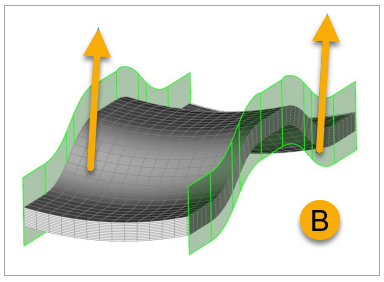
Note: When you generate a Solid Model from curved geometries and thick lay-ups, the boundary edges can be extruded in undesirable directions (A, below). An Extrusion Guide allows you to control the extrusion direction of the edges (B) using an edge set and a geometry or a direction vector. You can use multiple Extrusion Guides for one Solid Model. Using two edge sets, such as Edge1 and Edge2 in this tutorial, is the minimum requirement for properly defined composite solid models.
Create the second Extrusion Guide by following steps 10 to 12 above and using Edge2 as the Edge Set.
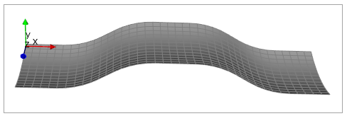
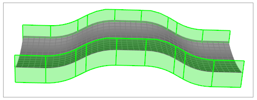
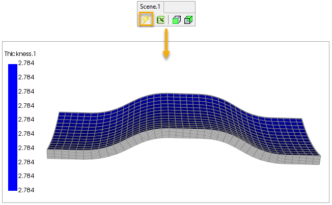
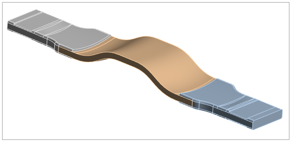
Click the Update icon on the toolbar. The composite model has been extruded into a solid structure.
Close the ACP window and go back to Workbench.
The following steps will guide you through assembling the solid composite part and the metal parts in Mechanical.
In this section, you will transfer the solid composite model data from ACP (Pre) and the provided metal part data from Metal Parts into Static Structural.
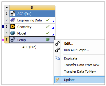
In Workbench, right-click the Setup cell in the ACP (Pre) system and select Update.
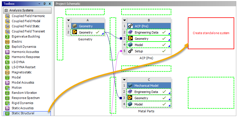
Under Analysis System in the Toolbox, click Static Structural and drop it into the Project Schematic pane.
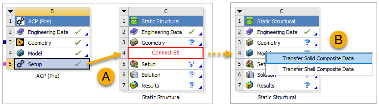
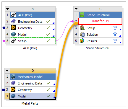
Click the B5 Setup cell and drop it onto the C4 Model cell to connect the two cells (A, below). When prompted, select Transfer Solid Composite Data (B).
Click the D4 Model cell and drop it onto the C2 Model cell to connect the two cells.
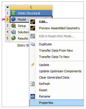
Right-click the Model cell in the Static Structural system and select Properties.
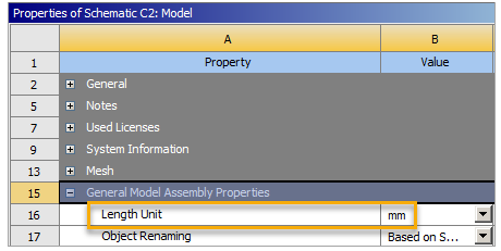
In the Properties of Schematic C2 dialog, expand General Model Assembly Properties. Change Length Unit to mm, then close the dialog.
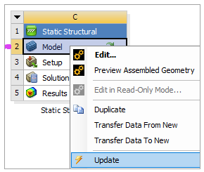
Right-click Model and select Update to finish the data transfer.
The contact regions between the solid composite part and the metal parts are automatically defined by Mechanical.
Note: For more information about contact regions, see Contact Region in the Mechanical Object Reference.
To check the contacts, follow the steps below:
In Workbench, double-click the Model cell in the Static Structural system to open Mechanical.

The meshes and materials of the solid composite part and the metal parts are imported from ACP (Pre) and Metal Parts analysis systems. You cannot modify them here.
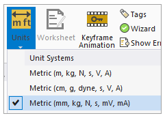
In Mechanical's Home tab, click Units and select Metric (mm, kg, N, s, mV, mA).
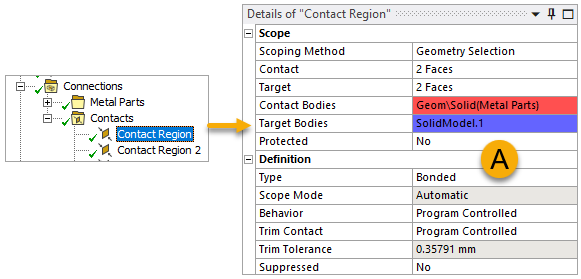
In the tree Outline, expand Connections and Contacts, then double-click Contact Region. The two contact regions used in this tutorial are Contact Region and Contact Region 2. The information of the first is shown in the Details pane (A, below). The contact body and the target body are visible in your model (B).
Note: Due to the auto-generation of contacts, some additional contact regions are created and automatically suppressed in this section. You may delete them without affecting the analysis.

Continue to check Contact Region 2 by following step 4 above.
In this section, you will add a Fixed Support to one end and a Remote Displacement to the other end of the model.
Note: For more information about Fixed Support and Remote Displacement, see Fixed Support in the Mechanical User's Guide and Remote Displacement in the Mechanical User's Guide.
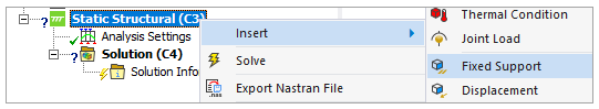
In the tree Outline, right-click Static Structural (C3), select Insert, then select Fixed Support.
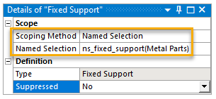
In the Details pane, choose Named Selection from the Scoping Method drop-down menu. Select ns_fixed_support(Metal Parts) as the Named Selection. Keep the other properties as default.
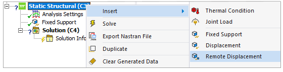
In the tree Outline, right-click Static Structural (C3), select Insert, then select Remote Displacement.
In the Details pane, choose Named Selection from the Scoping Method drop-down menu, then select ns_remote_displacement(Metal Parts) as the Named Selection (A, below).
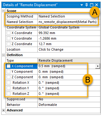
Define the X, Y, Z Components and the Rotation X, Y, Z values as shown (B, above).
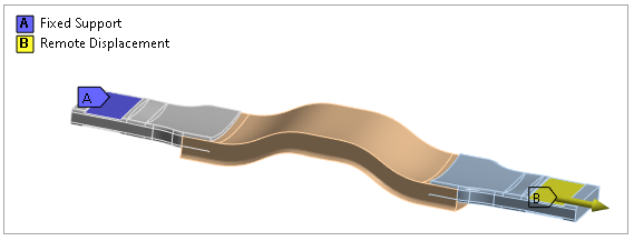
Click Static Structural (C3) in the tree Outline to view the Fixed Support and the Remote Displacement in your model.
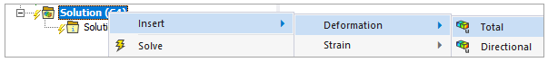
In the tree Outline, under Static Structural (C3), right-click Solution (C4). Select Deformation, then select Total.
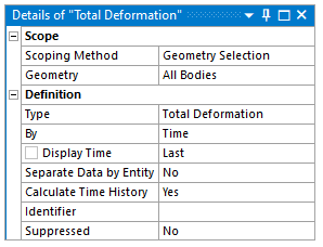
The Total Deformation's information is shown in the Details pane. Keep the properties as default.
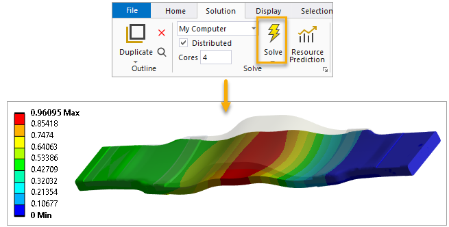
Switch to the Solution tab of the ribbon and click Solve. The assembly result is now visible in your model.
Close Mechanical and go back to Workbench.