In this section, you will configure the T-joint model's properties and create its five components.
The following steps will guide you through defining the Base Plate:
You will create Rosette.1, which is used to set the Reference Directions of the Base Plate's Oriented Selection Set (OSS).
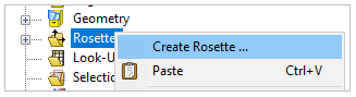
In the Tree View, right-click Rosettes and select Create Rosette.
In the Rosette Properties dialog, specify the Origin by placing the cursor in the field (A, below) and selecting any element on Plate2 of the model.
Note: The Origin coordinates will be slightly different from what is shown in this tutorial depending on which element you select on the model.
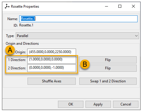
Specify the 1 Direction and 2 Direction (the X and Y directions of the Rosette) by entering the coordinates as shown (B).
Note: You can also specify the X and Y directions by choosing two nodes for each direction:
Place the cursor in the field.
Press Ctr and select the source node on the model.
Press Ctr and select the target node.
The coordinates will be slightly different from what is shown in this tutorial.
Click Apply to update the Rosette, then click OK to finish creating the first Rosette.
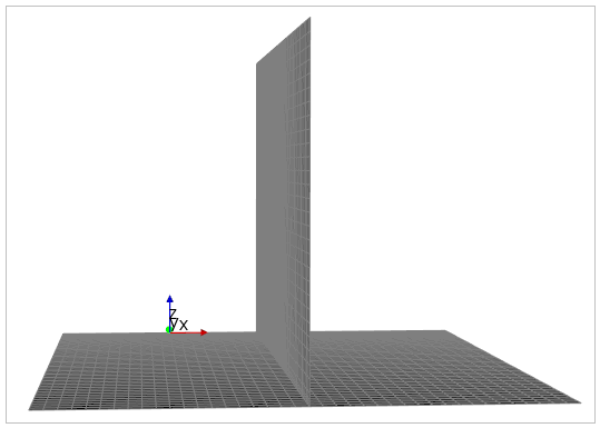
Note: To rotate the diagram, press and hold the scroll button, position the cursor at the center of the diagram, and move your mouse in the desired direction.
OSSs define the basis for lay-up definitions. The Orientation Direction of the OSS specifies the stacking direction of the modeling ply. The Reference Direction specifies the direction all ply angles are relative to.
Follow these steps to create an OSS for the Base Plate:
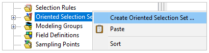
In the Tree View, right-click Oriented Selection Sets and select Create Oriented Selection Set.
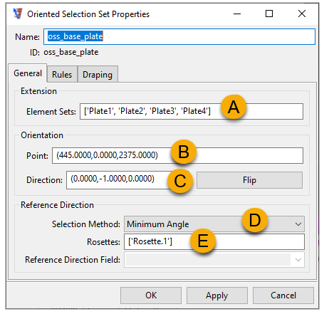
In the Oriented Selection Set Properties dialog, specify the Extension by placing the cursor in the Element Sets field (A, below), then selecting Plate1, Plate2, Plate3, and Plate4 from the Element Sets in the Tree View.
Tip: You can select multiple Element Sets by holding the Ctrl key.
Specify the Orientation Point by placing the cursor in the field (B), then selecting an element from the four plates of the model. Specify the Orientation Direction by entering the coordinates as shown (C).
Note: Similar to step 3 of the previous section, Defining the Rosette, you can define the Orientation Direction by choosing two appropriate nodes in the model.
Flipping the Orientation Direction will change the plies' build direction.
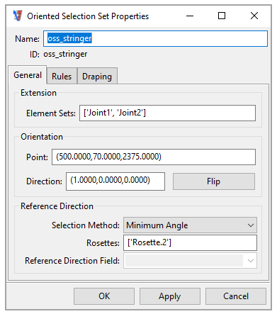
Specify the Reference Direction by choosing Minimum Angle for the Selection Method (D, above). Then specify Rosettes by placing the cursor in the field (E) and selecting Rosette.1 from the Rosettes in the Tree View.
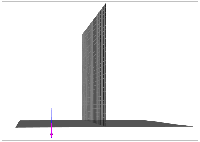
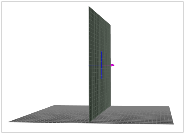
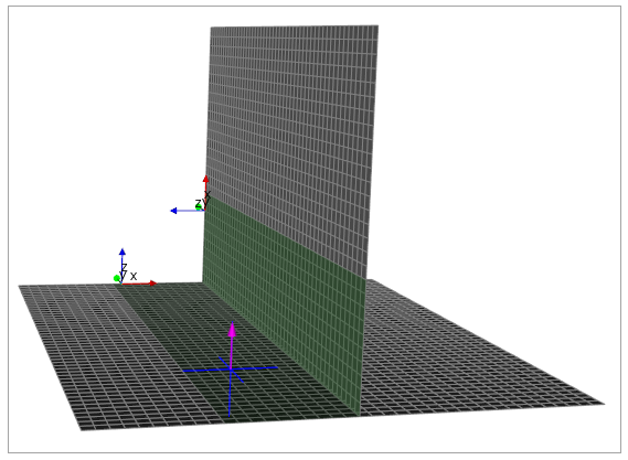
Click Apply to update the OSS. The OSS Orientation Point and Orientation Direction are shown below. Click OK to close the window.
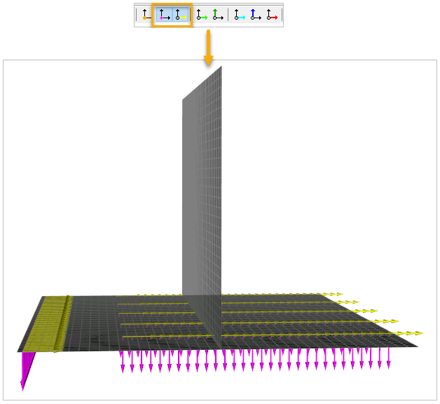
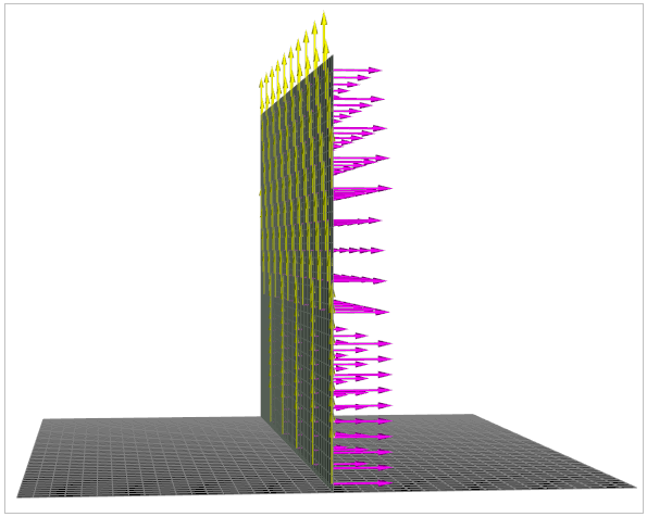
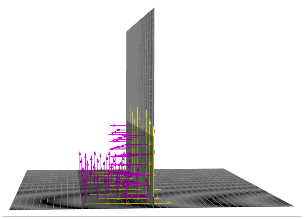
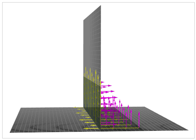
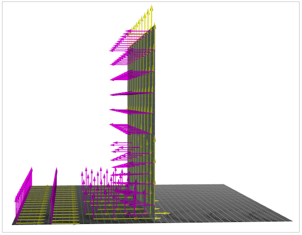
You can view the Base Plate's OSS Orientation and Reference Directions by activating the purple Show Orientations icon and the yellow Show Reference Direction icon on the toolbar.
Note:On ACP's toolbar, you can select the appropriate direction and visualization arrows as you build the model to view the normals, orientations, Reference Directions, and Fiber Directions. However, the graphic performance may decrease if many of those visualization options are activated.

The density and size visualization of the arrows might differ depending on the configuration of Plot Properties. You can view and edit those properties by clicking the icon on the toolbar shown below.
A section cut provides a visual depiction of the model's lay-up definition along an arbitrary section plane. Before creating the Base Plate's plies, you will define a section cut that allows you to examine and verify the layering of the plies in later steps.
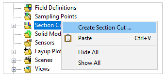
In the Tree View, right-click Section Cuts and select Create Section Cut.
In the Section Cut Properties dialog, edit the Position, Scoping, and Extrusion values. Click Apply.
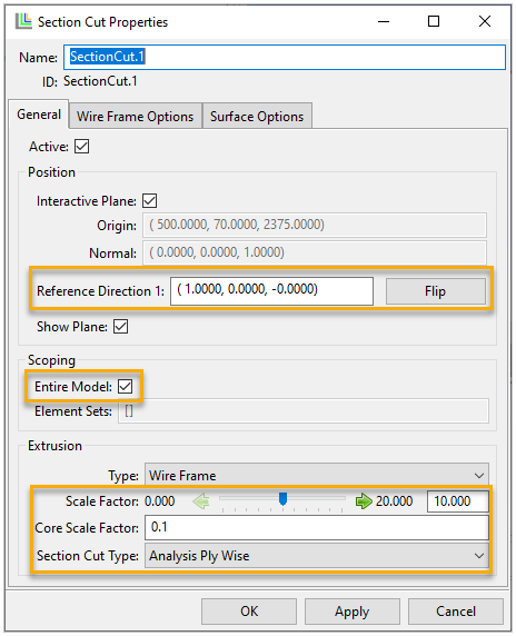
Note: For more information about the Section Cut properties, see Section Cuts in the ACP User's Guide.
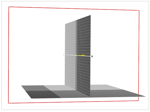
The section cut slices the model as shown below. Click OK to close the dialog.
The Basic Sandwich Panel Tutorial guides you through modeling a composite structure using Stackups and Sub Laminates. Here, the plies for a modeling component can also be created directly using a fabric in a Modeling Group. The Group provides efficient organization of Composite Definitions and streamlines your workflow without affecting the ply-ordering and definition. The lay-up is defined the same way as in production, where the first ply is the start of the stacking sequence.
You will create the Base Plate with six Epoxy Carbon UD plies, a core Honeycomb ply, and another six Epoxy Carbon UD plies.
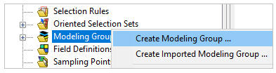
In the Tree View, right-click Modeling Groups and select Create Modeling Group.
In the Modeling Group Properties dialog, enter the Name and click OK.

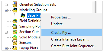
Under Modeling Groups, right-click Base_Plate and select Create Ply.
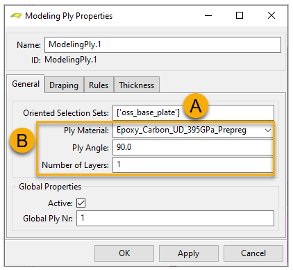
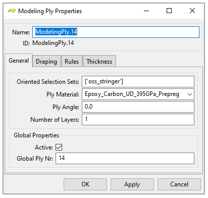
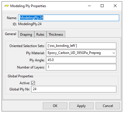
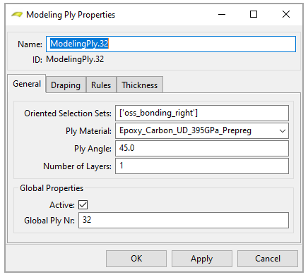
In the Modeling Ply Properties dialog, specify the Oriented Selection Sets by placing the cursor in the field (A, below), then selecting oss_base_plate from Oriented Selection Sets in the Tree View. Define the other properties as shown (B). Click Apply to update the ply, then click OK to close the dialog.
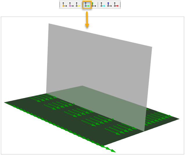
View the ply's Fiber Direction by activating the light green Show Fiber Directions icon on the toolbar.
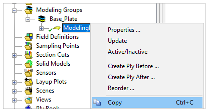
Right-click ModelingPly.1 in the Tree View and select Copy to copy the ply.
Tip: As a shortcut, you can simply select ModelingPly.1 in the Tree View and use the key command Ctrl+C.
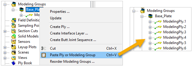
Right-click Base_Plate and select Paste Ply or Modeling Group to paste the ply. Repeat this step five times to have a total of six plies.
Tip: As a shortcut, you can simply select Base_Plate in the Tree View and use the key command Ctrl+V.
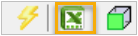
From the toolbar, click the Edit Entities with Excel icon.
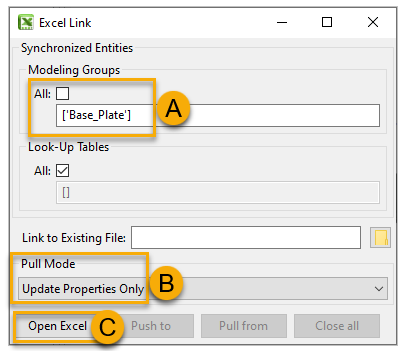
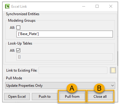
In the Excel Link dialog, specify Modeling Groups by deselecting All. Place the cursor in the field (A, below), and select Base_Plate from Modeling Groups in the Tree View.
Under Pull Mode, select Update Properties Only (B). Click Open Excel (C).
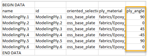
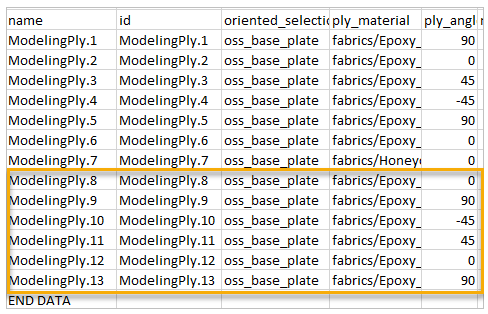
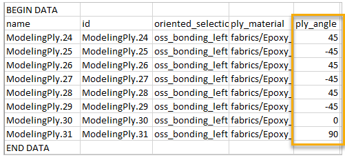
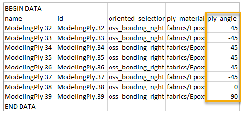
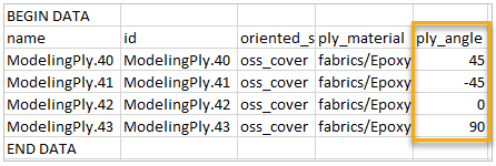
When Excel has launched, edit the ply angles by modifying the ply_angle column as shown below.
Note: You can manually edit the angle for each ply by double-clicking the ply in the Tree View and specifying the angle in the Modeling Ply Properties dialog.
In the ACP's Excel Link dialog, click Pull from (A, below), then click Close all (B).
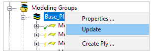
Under Modeling Groups, right-click Base_Plate and click Update to finish creating the first six Epoxy Carbon UD plies.
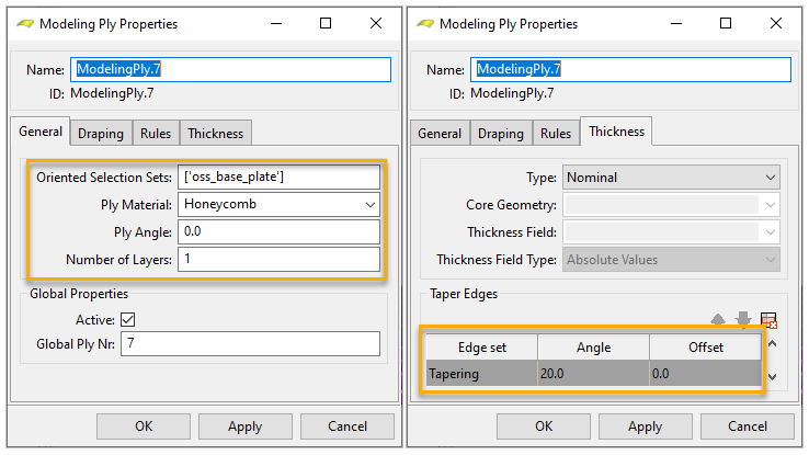
Create the core Honeycomb ply by following steps 3 and 4 above and using the specifications shown below. You will use the predefined Tapering Edge Set to taper the edges of the core by 20°.
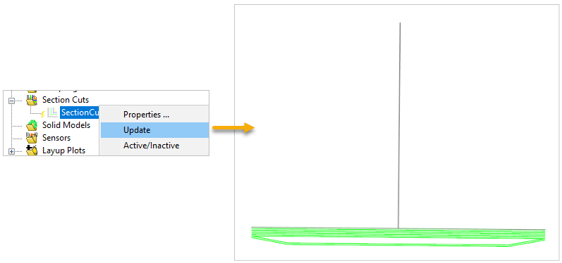
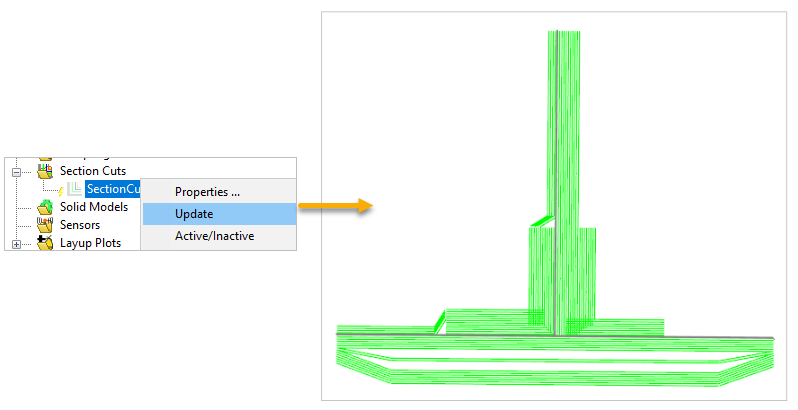
In the Tree View, expand Section Cuts, right-click SectionCut.1, and click Update to check the tapering of the core.
Create the last six Epoxy Carbon UD plies by following steps 6 to 13 above and using the specifications shown below.
Tip: In step 6, you can copy and paste multiple plies at the same time by following these steps:
Hold Ctrl and select multiple plies in the Tree View.
Right-click the plies and select Copy.
Right-click ModelingPly.7 and select Paste After.
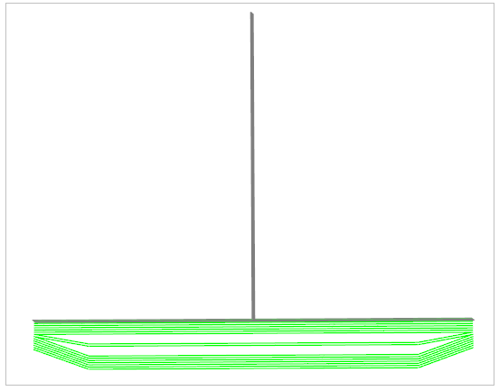
Update SectionCut.1 again to visualize your Base Plate's Section Cut.
The following steps will guide you through defining the Stringer:
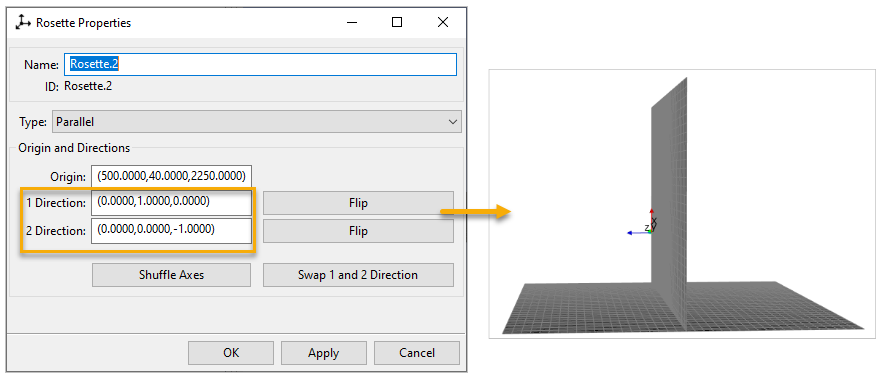
Create the second Rosette by following the steps in the earlier section, Defining the Rosette. The Origin of Rosette.2 can be any element on Joint1 of the model. Enter the coordinates or select the appropriate nodes in the model for 1 Direction and 2 Direction as shown below.
Create the Stringer's OSS by following the earlier instructions in Defining the Base Plate's Oriented Selection Set. For the Orientation Point, select any element on Joint1 or Joint2. Specify the other properties as shown below.
The Stringer's composite lay-up consists of ten Epoxy Carbon UD plies. Create the plies by following the earlier instructions in Defining the Base Plate's Plies. Use the specifications shown below.
You will create the Left Bonding by defining its OSS and plies as described in the following sections:
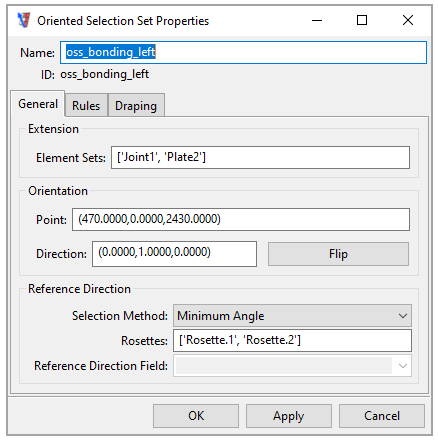
Create the Left Bonding's OSS by following the earlier instructions in Defining the Base Plate's Oriented Selection Set. Choose any Plate2 element for the Orientation Point. Specify the other properties as shown below. You will use two Rosettes for this OSS.
Note: You can use multiple Rosettes to specify the direction of an OSS. The X direction of each Rosette controls the OSS direction. Using multiple Rosettes allows varying reference directions on complex geometries. You will use the angle (minimum or maximum) between the element lay-up orientation and the Z direction of each Rosette as a criterion to select the appropriate Rosettes.
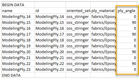
The Left Bonding's composite lay-up consists of eight Epoxy Carbon UD plies. Create the plies by following the earlier instructions in Defining the Base Plate's Plies. Use the specifications shown below.
The following steps will guide you through defining the Right Bonding:
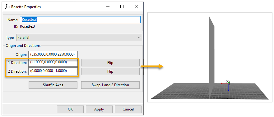
Create the third Rosette by following the steps in the earlier section, Defining the Rosette. The Origin of Rosette.3 can be any element on Plate3 of the model. Enter the coordinates or select the appropriate nodes in the model for 1 Direction and 2 Direction as shown below.
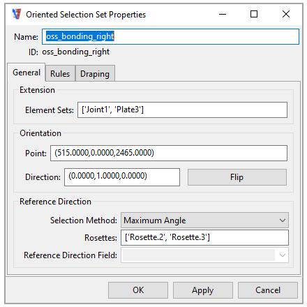
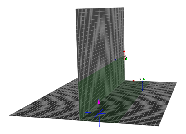
Create the Right Bonding's OSS by following the earlier instructions in Defining the Base Plate's Oriented Selection Set. Select any Plate3 element for the Orientation Point. Specify the other properties as shown below. Choose the Maximum Angle and two Rosettes for this OSS.
Note: Because of the angles between the elements' orientations and the Rosettes' Z directions here, if you choose Minimum Angle, ACP (Pre) will be unable to determine an element's Reference Direction and will use an alternate computational method. You will receive a warning message when this happens.
For more information about the Selection Method for Reference Direction, see Reference Direction in the ACP User's Guide.
Tip: In this tutorial, you have used Named Selections as Element Sets to create the Left and Right Bondings' OSSs. Another option is to use Selection Rules to define the extents of the bonding areas. This is a key strength of ACP that can help eliminate the tedious work of defining and maintaining multiple Named Selections when you design complex laminates or scale up the model.
To learn more about Selection Rules, see Selection Rules in the ACP User's Guide, or practice using the feature in the Selection Rules Tutorial.
The Right Bonding's composite lay-up consists of eight Epoxy Carbon UD plies. Create the plies by following the earlier instructions in Defining the Base Plate's Plies. Use the specifications shown below.
You will create the Cover by defining its OSS and plies as described in the following sections:
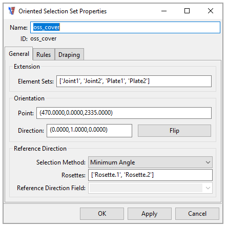
Create the Cover's OSS by following the earlier instructions in Defining the Base Plate's Oriented Selection Set. Select any Plate1 or Plate2 element for the Orientation Point. Specify the other properties as shown below. You will use two Rosettes for this OSS.
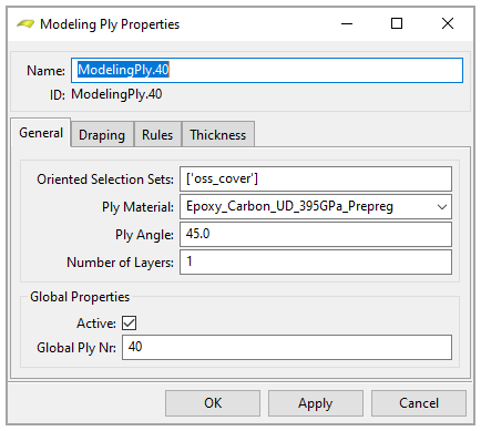
The Cover's composite lay-up consists of four Epoxy Carbon UD plies. Create the plies by following the earlier instructions in Defining the Base Plate's Plies. Use the specifications shown below.
Review the model's final composite lay-up by looking at the Section Cut, Angle Plot, Thickness Plot, and Sampling Point.
To view the Section Cut, expand Section Cuts in the Tree View, right-click SectionCut.1, and click Update.
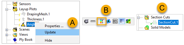
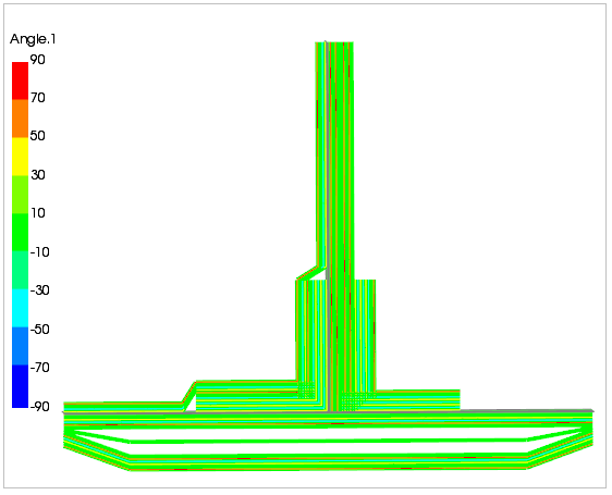
To view the Angle Plot, right-click Angle.1 from the Layup Plots and click Update (A, below). Activate the Show Legend icon from the toolbar (B), then click SectionCut.1 (C) to show the plot.
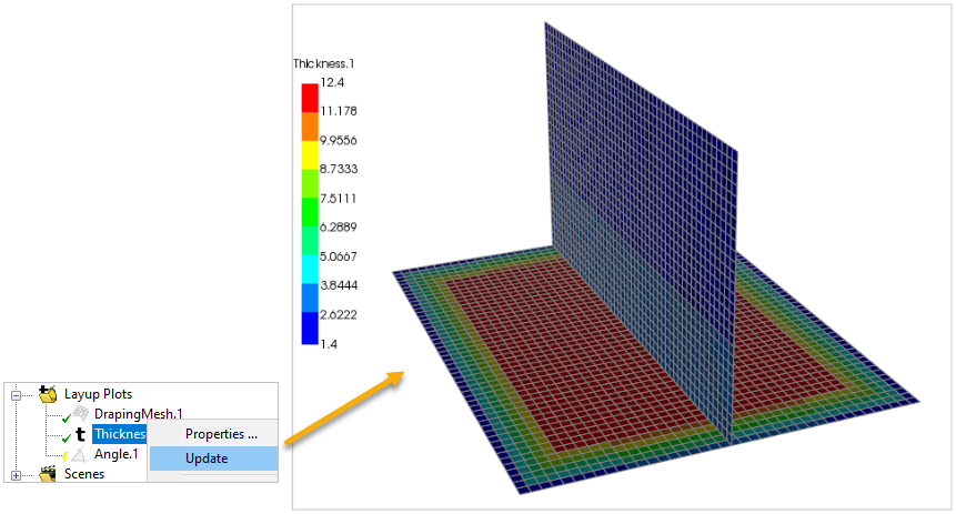
To view the Thickness, right-click Thickness.1 from the Layup Plots and click Update.
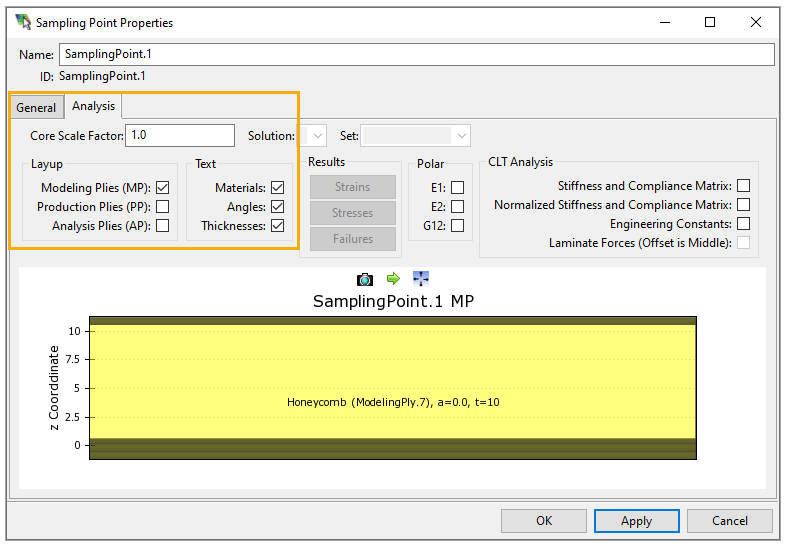
Use the Sampling Point to access the ply-wise results. You may view the through-the-thickness data of any point in the model by following the instructions in the previous tutorial, Through-the-Thickness Plot in ACP. Specify its properties in the Analysis tab of the Sampling Point Properties dialog as shown. The plot below displays data of the Sampling Point
(490,0,2360)with the Sampling Direction(0,-1,0).