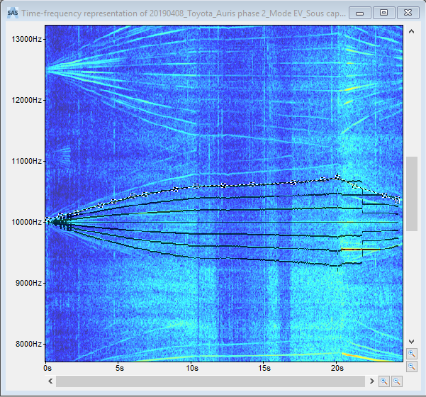
Detecting PWM Harmonics

This procedure shows how to identify and select "V shape" excitations (PWM tones) emitted around the constant PWM frequency in PWM noise to modify them.

To Detect PWM profile:

Prerequisites: You need to open or calculate a time frequency representation.
  1. To enhance the representation readability,
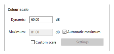
    • In the Colour scale panel under Current Display and Tool Settings, increase the Dynamic in decibels and check Automatic maximum.

    • From Preferences, change the window type.

    • Adjust the time-frequency window.

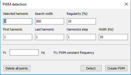
  2. In the toolbar, click PWM detection .

    The PWM detection window is displayed and the harmonics selection tool is enabled.

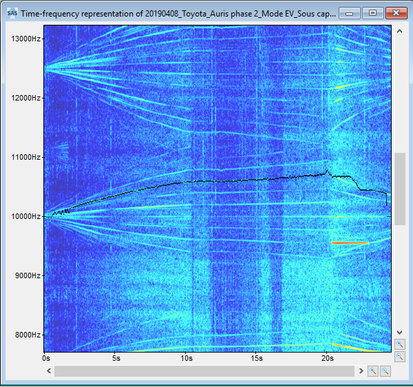
  3. In the representation, click several points on one harmonic from the start of the signal (0 second) to end of the signal.

    Several points are selected on the harmonic.

  4. In the PWM detection window, set the:
    • number of selected harmonic from the Select harmonic field.

    • thickness of an area around the selected harmonic from the Search width field.

    • smoothness of the curve from the Regularity field.

    • rank (or number) of the first harmonic to be detected from the First harmonic field.

    • rank of the last harmonic to be detected from the Last harmonic field.

    • step between two harmonics from the Harmonic step field.

    • the thickness of the selected path from the Width field.

    • Enter a PWM constant frequency in Hertz in the Fc field.

  5. Once the detection parameters defined, click:
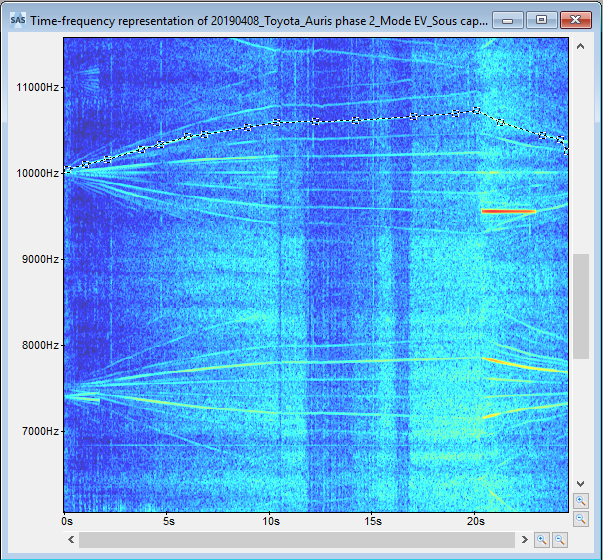
    • Detect to select the PWM tone(s) depending on the user-defined parameters.

    • Create PWM to create a PWM profile and associate it to the current representation.

  6. If needed, click Delete all points to undo the PWM selection points.

    The harmonics are detected.

    Tip: Now, you can isolate, listen and save the detected PWM tones. You may apply additional modifications to the detected PWM tones for example sending to temporal window, changing the commutation frequency or shifting frequency.