


3D View
With Preferences, you can define parameters of the 3D display. This is useful to have a more precise view to parametrize the meshing.
In Radial Mesh Control group box, you can type the regular subdivisions and the adaptative subdivisions values.
In Mesh reference group box, you must select Geosphere or Sphere theta/phi.
With high values, the loading time is bigger.
By selecting the Antialiasing check box, you can have a better drawing of lines in 3D view by avoiding notched lines.
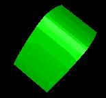
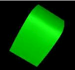
By selecting the Phong check box, you can display 3D view without meshing.
Warning: Selecting the Phong check box can cause some problems with ellipsoid, which do not appear in shading view, and with OSB files if normals have wrong orientation.
 |
 |
Without phong |
With phong |
By selecting the Triangle check box, you can have a better way to mesh the object.
Warning: If some problems occur when displaying the 3D view, you must click to clear the check box.By selecting the UV Axis & Normals check box, you can display UV axis of each face used for texture on OSB faces.
Normals is used to define the orientation convention for BSDF.
In the 3D view, red and green axis of each faces represent the UV system and blue axis the normal. The system can be direct or indirect.
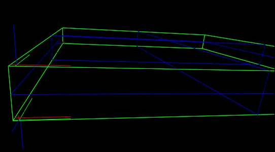
The blue axis which is displayed gives the emission direction for the emissive surfaces and indicates the convention for the 180° BSDF. The direction related to the blue axis is used for the angles with incidence from 0 to 90° of the BSDF.
If this direction does not fit, on the OSB it is possible to change the selected face orientation with the Invert normal contextual menu which changes the OSB face topology.
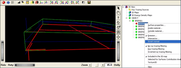
By selecting the UV Isos 0.5 check box, you can display the Isos at U=V=0.5 which correspond to the blue lines in the 3D view.
In the Number of first pattern to display (TXT texture) and Number of patterns to display (TXT texture) boxes, you can type values which are used to display a TXT texture.
If the first value is N0 and the second one N, all the patterns in the text file between N0 and N0+N-1 are displayed.
In the Number of repetitions to display (Brep texture) box, you can type a value which is used to display a Brep texture.
When defining a system including a huge number of patterns, it is not possible to display all these patterns in the 3D view. Using the number of patterns or the number of repetitions, you can display a part of the texture to check visually your texture definition.