


Parameters of Scattering Surface
From Scattering Surface Curve, you can set the following parameters:
Display
View shading to display a shading view of the intensity envelope.
View Mesh to display the intensity envelope with wireframe.
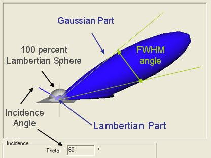
Pure Lambertian curve to display the pure Lambertian curve.
Incident direction to display the incident direction.
Tangent plane to display the tangent plane.
Axis System to display the axis System.
Decorations to display the 3D view tool.
For more details, you can view Using 3D view tool.
BRDF to display the BRDF.
Probability density to display the probability density.
Logarithmic View to display the logarithmic view.
 , you can edit
 Incidence
With Incidence group box, you can view the incidence dependency (theta and phi).
Wavelength
With Wavelength group box, you can view the wavelength dependency.
Optical Properties
With Optical properties group box, you can modify optical properties.
Anisotropy Vector
Check how your part with anisotropic property is located and oriented depending of your CSYS of your main assembly.
Modify the angle by transferring Matrix between the main coordinates and the local one (your part).
Your vector will be calculated and set in the Anisotropy vector.
or
Create, into your part, the vector (line or axis) that you want to have for the orientation of your reference (0° anisotropic angle on your surface).
Use the information of your line referenced into the main assembly.