Geometry Command
The Fields Calculator Geometry command opens a dialog box that lets you select a geometry to load into the top register of the calculator.
Use the Geometry dialog box to do the following:
- Find the value of derived field quantities on any point, line, surface, or volume
- Plot quantities directly from the calculator
- Display a previously defined isosurface, maximum or minimum field point using the Draw command
The following types of geometries are available:
|
Point - See drawing a point object. Points you draw are listed in the history tree, and in the Calculator Geometry dialog when you select Point. |
|
Line- See drawing a line object. Lines you draw are listed in the history tree, and in the Calculator Geometry dialog when you select Line. To set the number of points on a line, see Geom Settings. |
|
Surface - Sheet objects and face lists which you can make, are listed under surface in the history tree and in the Calculator Geometry dialog when you select Surface. Due to the ambiguity of the normal vector of a sheet, the result may require a multiplication by ( 1 ) or ( -1 ). |
|
Volume - 3D objects, Regions, and object lists of 3D objects including AllObjects are available in the Calculator Geometry dialog when you select Volume. |
|
Coord - Coordinate systems are available in the Calculator Geometry dialog when you select Coord. |
To load a geometry into the calculator:
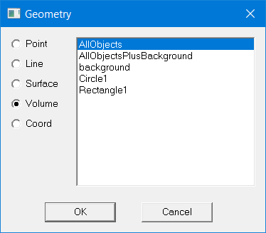
- In the Fields Calculator, click Geometry.
The Geometry dialog box appears.
- Select a geometry type.
- Non-convex 3D non-model solids are not supported for Field Overlay Plots and Fields Calculator computations.
- Object lists containing non-model object(s) are supported for Field Overlay Plots but are not supported for Fields Calculator computations.
- Click the geometry.
- Click OK to load the geometry.
A list of all available geometries appears.
Background Geometry
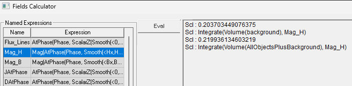
For 2D solver simulations that include a Balloon boundary condition, the Geometry dialog box includes entries for background and AllObjectsPlusBackground. The background is the part that is outside the geometry but on which the solver generated a mesh.
Including the background in the calculation will affect the results as demonstrated in the following figure: