
CAD Integration through Workbench
Ansys Electromagnetics CAD integration is a Workbench feature available for Ansys Electromagnetics 3D Products - HFSS, Maxwell, and Q3D as the Ansys Framework for Ansys Electromagnetics package. This feature is available only through Workbench, and is not available in standalone Ansys Electromagnetics products.
Ansys Electromagnetics CAD integration provides a bidirectional dynamic link through Workbench, which makes it possible to get updated geometry from CAD, to modify the CAD parameters in Ansys Electromagnetics products, and return updated geometry. The feature is non-associative due to a need to reassign boundaries if the modified CAD model is to be used. The process creates a User Defined Model (UDM) for each geometry source:
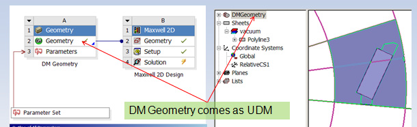
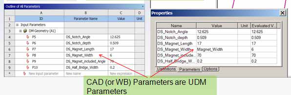
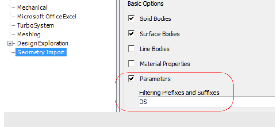
The User Defined Model (UDM) format makes it possible to exchange parameters.
For further description of the UDM feature and function, see User-Defined Model (UDM).
Ansys Electromagnetics CAD integration makes it possible to consume geometry from multiple upstream source which can be any CAD or Ansys Electromagnetics product. This feature supports direct interfaces with all major CAD systems:
- Creo Parametric
- UG NX
- CATIA V5
- SOLIDWORKS
- Autodesk Inventor
- Ansys Design Modeler (DM)
- Ansys SpaceClaim Direct Modeler (SCDM)
CAD software must be installed on user machine
- Not required on solve nodes
Platforms Supported:
- Windows 64 bit
- Linux
Related Topics:
CAD Integration and Geometry Sharing
Bi-Directional CAD Integration