
CAD Integration and Geometry Sharing
CAD model comes into Ansys Electromagnetics as User Defined Model (UDM).
The input to Ansys Electromagnetics from CAD is
- Geometry/Topology with persistent IDs
- CAD parameters
- Material assignment
- Attributes like name, and color
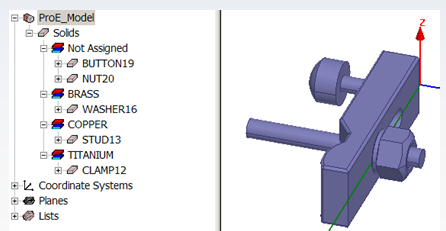
For example, in Workbench, a Pro/E Model can be linked to HFSS:

The geometry can then be viewed in HFSS as a UDM:
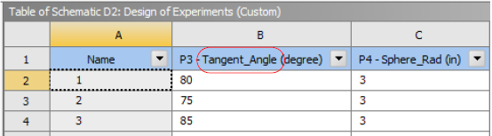
The CAD or WB model parameters appear in the Workbench:
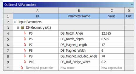
Though the Ansys Electromagnetics CAD Integration, the linked UDM includes the same parameters.
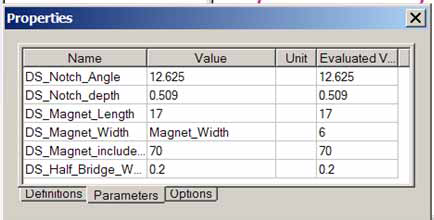

After you import a geometry with parameters to an Electromagnetics application in the desktop, you need to map them to local variables. That is, in the target Electromagnetics application, select the geometry associated with the parameters. Update the geometry, and view the Parameters tab in the Property window. The Values column will show the values of the imported parameters. You then type names for local variables in the values column.
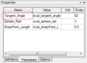
When you have local variables for the imported Design Modeler parameters, you are ready to use Design Xplorer for multiple design parameters.
Related Topics
Ansys Electromagnetics CAD Integration Through Workbench